Microchannel liquid cooling heat radiator and conduction cool plug for high heat flux chip

A high heat flux density, micro-channel technology, applied in the direction of electric solid-state devices, semiconductor devices, semiconductor/solid-state device components, etc., can solve the problem of rising heating power, reduce contact thermal resistance, facilitate heat dissipation, and improve heat exchange efficiency effect

Active Publication Date: 2016-12-21
BEIJING INST OF RADIO MEASUREMENT
View PDF4 Cites 18 Cited by
  • Summary
  • Abstract
  • Description
  • Claims
  • Application Information

AI Technical Summary

Problems solved by technology

[0004] However, the current application of ultra-large-scale gate array chips and transmitting and receiving chips has caused the heating power of the chip itself to rise sharply, and the local heat flux can even reach more than 500W / cm. Therefore, integrated circuit design and structural / thermal design need to be carried out at the same time , to carry out collaborative design to meet the heat dissipation requirements of existing chips

Method used


Image

  • Microchannel liquid cooling heat radiator and conduction cool plug for high heat flux chip
  • Microchannel liquid cooling heat radiator and conduction cool plug for high heat flux chip
  • Microchannel liquid cooling heat radiator and conduction cool plug for high heat flux chip

Examples


Embodiment 1

[0031] Such as figure 1 As shown, a micro-channel liquid cooling heat sink for high heat flux density chips of this embodiment is fixedly mounted on one side of the chip 3; it includes a chip packaging board 1, a cover plate 2 and a cooling liquid circulation device. The chip packaging board 1 is packaged and fixed on one side of the chip 3, the edge of the other side of the chip packaging board 1 and the edge of the cover plate 2 are sealed and fixedly connected, the chip packaging board 1 and the cover A circulation cavity is formed between the plates 2, the chip packaging board 1 is provided with a plurality of heat dissipation teeth 11 on one side of the circulation cavity; the cover plate 2 is provided with a liquid inlet 21 and a liquid outlet 22 The liquid inlet hole 21 and the liquid outlet hole 22 are respectively communicated with the cooling liquid circulation device through a liquid cooling pipe 8. The liquid cooling pipe in this embodiment is a semi-rigid water pip...

Embodiment 2

[0040] A conductive cooling plug-in of this embodiment includes a plug-in body and the micro-channel liquid cooling heat sink as described in Embodiment 1. The chip packaging board 1, the cover plate 2 and the chip 3 are all fixed inside the plug-in body, The cooling liquid circulation device is located outside the plug body. The conductive cold insert in this embodiment is a VPX conductive cold insert.

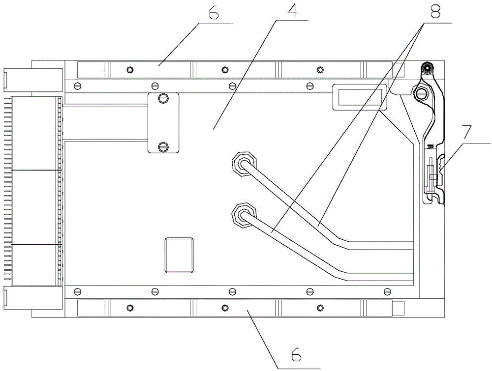
[0041] Such as figure 2 with image 3 As shown, the plug-in body of this embodiment includes a plug-in cold plate 4 and a printed board 5. The plug-in cold plate 4 is fixedly connected to the printed board 5 by screws, and the micro-channel liquid cooling radiator is fixed on Between the plug-in cold plate 4 and the printed circuit board 5. A wedge-shaped locking device 6 is provided on the outer edge of the plug-in cold plate 4, a handle 7 is provided at one end of the plug-in cold plate 4, and the plug-in cold plate 4 is locked and fixed to the chassis by the wedge-shaped l...


PUM


Abstract

The invention relates to a microchannel liquid cooling heat radiator and a conduction cool plug for a high heat flux chip. The microchannel liquid cooling heat radiator is fixedly arranged on one side of the chip, and comprises a chip package plate, a cover plate and a cooling liquid circulation device. The chip package plate is packaged and fixed on one side of the chip. The edge of the other side of the chip package plate and the edge of the cover plate are sealed and fixedly connected. A circulation cavity is formed between the chip package plate and the cover plate. A number of heat radiating teeth are arranged on one side of the chip package plate in the circulation cavity. The cover plate is provided with a liquid inlet hole and a liquid outlet hole. The liquid inlet hole and the liquid outlet hole are respectively communicated with a cooling liquid circulation device through liquid cooling pipes. According to the heat radiator provided by the invention, a microchannel heat radiating structure with a number of heat radiating teeth is arranged on one side of the chip package plate in the circulation cavity; the contact heat resistance is reduced; the heat exchange efficiency is improved; and the heat radiator is favorable for heat radiating of the high heat flux density heating chip and other concentrated heat sources.

Description

Technical field [0001] The invention relates to a liquid cooling radiator, in particular to a microchannel liquid cooling radiator and a conductive cooling plug-in for a chip with a high heat flux density. Background technique [0002] With the increasing integration of plug-ins, the heat dissipation problem of power chips with high / ultra-high heat flux density on plug-in printed boards has become the focus of structural design and thermal design research. [0003] Traditional heat conduction methods include air cooling and liquid cooling. Most of the heat dissipation is after the chip is packaged, the heat of the heating chip is taken away by the cold plate, and the surface of the cold plate and the heating chip is reduced by thermal pads or thermal grease Contact thermal resistance, at the same time, the cold plate can be a conduction cooling type or a liquid cooling type with a coolant flow channel inside. This method has a relatively simple structure design and high reliability...

Claims


Application Information

Patent Timeline
Patent Type & Authority Applications(China)
IPC IPC(8): H01L23/367
CPCH01L23/367
Inventor 郑若隐
Owner BEIJING INST OF RADIO MEASUREMENT
Why Eureka
Try Eureka