Strain type sensor and manufacturing method thereof
A technology of a strain gauge sensor and a manufacturing method, which is applied in the direction of instruments, measuring devices, measuring force, etc., can solve the problems of sensor stability, poor precision, incapable of mass production, poor zero point stability, etc., and achieve good insulation, Easy to purchase, easy to process and produce
- Summary
- Abstract
- Description
- Claims
- Application Information
AI Technical Summary
Problems solved by technology
Method used
Image
Examples
Embodiment 1
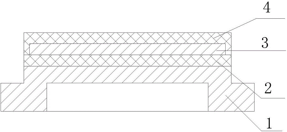
[0054] Such as figure 1 and Figure 4 As shown, the strain sensor of the present invention includes an elastic base 1, an insulating medium layer 2 covering the elastic base 1, and a conductive film layer 3 covering the insulating medium layer 2, and a resistance bridge 5 is arranged on the conductive film On the layer 3, an insulating protective layer 4 is provided on the conductive film layer 3 and the insulating medium layer 2, the number of layers of the insulating medium layer 2 is at least one layer, and the number of layers of the insulating protective layer 4 is at least for one layer.
[0055] In this embodiment, the insulating medium layer 2 can be multilayer, and the insulating medium layer 2 of the multilayer is the same or different insulating medium, and the insulating protection layer 4 can be multilayer, and the insulating protection layer 4 of the multilayer can be multilayer. Layer 4 is the same or different insulating medium. The shape of the elastic matr...
Embodiment 2
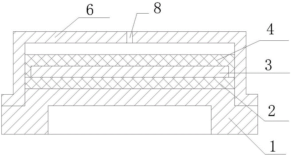
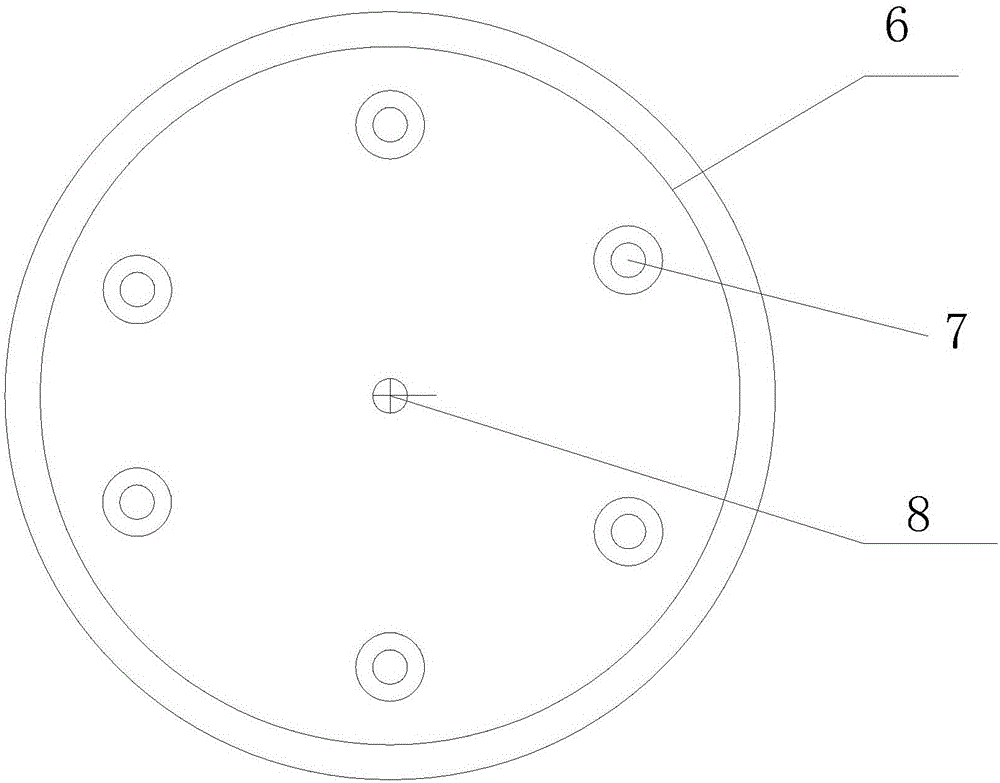
[0059] The only difference between this embodiment and Embodiment 1 is that the strain gauge sensor also includes a protective cover 6 arranged on the insulating protective layer 4, and the protective cover 6 is provided with a lead-out wire for the resistance bridge 5. The lead-out hole 7, the thickness of the protective cover 6 is 0.05mm-10mm, and the distance between the inner surface of the top of the protective cover 6 and the upper surface of the insulating protection layer 4 is 0.05mm-10mm.
[0060] In this embodiment, the protective cover 6 is provided with a ventilation hole 8, and the ventilation hole 8 is an oval hole, a rectangular hole or a regular polygonal hole.
[0061] In this embodiment, the lead-out hole 7 is a circular hole, the diameter of the lead-out hole 7 is 0.3 mm to 5 mm, and the length of the lead-out line is 1 mm to 100 mm; the ventilation hole 8 is a circular hole , The diameter of the vent hole 8 is 0.1mm˜10mm.
Embodiment 3
[0064] This embodiment includes the following steps:
[0065] Step 1, pretreatment of the elastic matrix: when the elastic matrix 1 is 304 stainless steel or 316L stainless steel, the first choice is to carry out stress relief annealing treatment on the elastic matrix 1, wherein, the temperature of the stress relief annealing treatment is 475 ° C, and the stress relief annealing treatment The time is 4 hours; then, the surface of the elastic matrix 1 after the stress relief annealing treatment is ground, the specific process is: select an abrasive with a particle size of 17 μm, and grind the surface of the elastic matrix 1 that has been heat-treated in step 101 until it becomes elastic The roughness of the upper and lower surfaces of the substrate 1 is 0.8 μm to 1.6 μm; finally, decontamination and drying are performed on the ground elastic substrate 1; the thickness of the elastic substrate 1 is 50 mm;
[0066] In the actual production process, the elastic matrix 1 is degreas...
PUM
| Property | Measurement | Unit |
|---|---|---|
| thickness | aaaaa | aaaaa |
| thickness | aaaaa | aaaaa |
| thickness | aaaaa | aaaaa |
Abstract
Description
Claims
Application Information
 - Generate Ideas
- Intellectual Property
- Life Sciences
- Materials
- Tech Scout
- Unparalleled Data Quality
- Higher Quality Content
- 60% Fewer Hallucinations
Browse by: Latest US Patents, China's latest patents, Technical Efficacy Thesaurus, Application Domain, Technology Topic, Popular Technical Reports.
© 2025 PatSnap. All rights reserved.Legal|Privacy policy|Modern Slavery Act Transparency Statement|Sitemap|About US| Contact US: help@patsnap.com


