Assembling plate for metal guide pin connector

A technology of guide pin connector and tooling board, which is applied in the manufacture of contact boxes/bases, etc., can solve the problems of low product qualification rate, low assembly accuracy, and debris left, and achieve high product qualification rate and assembly accuracy. High, less debris leftover effect

Active Publication Date: 2016-12-14
山东云特信息科技有限公司
View PDF6 Cites 0 Cited by
  • Summary
  • Abstract
  • Description
  • Claims
  • Application Information

AI Technical Summary

Problems solved by technology

[0003] The purpose of the present invention is to overcome the shortcomings of the prior art, to seek an assembly method for the metal guide pin connector and the tooling board used, and to solve the problem of sticking after sintering and missing assembly caused by debris left in the existing assembly method. High efficiency, low assembly accuracy, low product qualification rate and low productivity

Method used


Image

  • Assembling plate for metal guide pin connector
  • Assembling plate for metal guide pin connector
  • Assembling plate for metal guide pin connector

Examples


Embodiment 1

[0022] The metal guide pin connector tooling plate involved in this embodiment includes a first tooling plate 5 and a second tooling plate 9; the first tooling plate 5 and the second tooling plate 9 are equal in length and width to the bottom mold 1 of the graphite mold, and the first The lower surface of the tooling plate 5 is provided with protrusions 6 arranged in an array. The height of the protrusions 6 is not lower than the difference between the depth of the sintering sinker 2 on the bottom mold 1 of the actual graphite mold and the thickness of the metal shell 4. If the height of the protrusions 6 If it is too low, the metal shell 4 is likely to shake during the flipping process of assembly, the position of the solder hole 3 is shifted, a through hole 7 is provided on each protrusion 6, and 4 cylinders are provided on the upper surface of the first tooling plate 5 Shape limit bolt 8, the limit bolt 8 and the through hole 7 are distributed in a staggered manner, and the ...

Embodiment 2

[0031] The metal guide pin connector tooling board involved in this embodiment is equipped with an automatic weighing sensor at the bottom of the cylindrical counterbore 10 on the second tooling board, and the automatic weighing sensor is connected to the central control terminal, and the central control terminal is connected to the mechanical arm and the embodiment 1. Except for the metal guide pin connector tooling board, the other structures are the same.

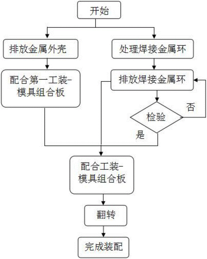
[0032] The assembly method of the metal guide pin connector involved in this embodiment, its specific process includes the following steps:

[0033] (1), discharge the metal shell: put the bottom mold 1 of the graphite mold into the shock sorter, and then disperse and put the metal shell 4 of the metal guide pin connector with a quantity greater than the number of the sintering sinker 2 on the bottom mold 1 of the graphite mold, The depth of the sintering sink 2 on the bottom mold 1 of the graphite mold can only discharg...


PUM


Abstract

The invention belongs to the technical field of metal-glass packaging and relates to an assembling plate for a metal guide pin connector. The assembling plate comprises a first assembling plate and a second assembling plate, wherein sintering sediment slots are distributed in an array form in a graphite jig bottom mold; bulges are distributed in the array form on the lower plate surface of the first assembling plate; through holes are formed in the bulges; cylindrical limiting bolts are arranged on the upper plate surface of the first assembling plate; the limiting bolts and the through holes are distributed in a staggered form; cylindrical sediment holes and cylindrical limiting through holes are distributed in the array form on one surface of the second assembling plate; a metal shell is arranged in the sintering sediment slots of the graphite jig bottom mold; welding metal rings are arranged in the cylindrical sediment holes; the sintering sediment slots are correspondingly clamped with the bulges; the metal shell welding holes, the through holes and the cylindrical sediment holes are successively and correspondingly communicated with each other; the limiting bolts are inserted into the limiting through holes. The assembling plate has the advantages of reduction of splashing and adhering phenomena after sintering, low neglected loading rate, high assembling accuracy, high product yield, reasonable assembling process, suitability for large-scale production and high economic benefit.

Description

technical field [0001] The invention belongs to the technical field of metal-glass packaging, and relates to a tooling board for a metal guide pin connector. The solder hole, the through hole and the cylindrical counterbore are correspondingly connected in sequence, and the assembly of the metal guide pin connector parts is automatically realized. Background technique [0002] As one of the key components of integrated circuits, metal-glass packaged metal guide pin connectors can meet the requirements of high-power circuits, high-low frequency circuits and various hybrid integrated circuits in aerospace, aviation and other fields. The functions of signal transmission, heat dissipation, sealing and chemical protection can effectively improve the reliability of the circuit and reduce the cost of the circuit; the metal shell of the metal guide pin connector is equipped with a grounding edge line, which also plays a vital role in improving the reliability of the circuit. . The...

Claims


Application Information

Patent Timeline
Patent Type & Authority Applications(China)
IPC IPC(8): H01R43/18
CPCH01R43/18
Inventor 王舜华张云飞曹侠
Owner 山东云特信息科技有限公司
Why Eureka
Try Eureka