Surface plasmon meta-material based multi-frequency high-gain electric small antenna and array

A technology of surface plasmon polaritons and electric small antennas, which is applied in the directions of antenna arrays, antenna arrays, and antennas that are energized separately. It can solve the problems of low gain, low conversion efficiency, and large overall size of electric small antennas, and achieve stable gain. , low cost and light weight

Inactive Publication Date: 2016-12-14
SHANGHAI UNIV
View PDF2 Cites 2 Cited by
  • Summary
  • Abstract
  • Description
  • Claims
  • Application Information

AI Technical Summary

Problems solved by technology

In addition, if a rectifier or capacitor is directly connected in series with the sub-wavelength unit, there will also be a problem of low conversion efficiency due to the extremely low input power
The fourth category is to use electrically small-sized metamaterial antennas and form an array, but the existing working electrically small antennas have low gain, and work in single or dual frequency, and the unit spacing is still limited to about 0.5λ when forming an array. Overall size is still large

Method used


Image

  • Surface plasmon meta-material based multi-frequency high-gain electric small antenna and array
  • Surface plasmon meta-material based multi-frequency high-gain electric small antenna and array
  • Surface plasmon meta-material based multi-frequency high-gain electric small antenna and array

Examples


Embodiment 1

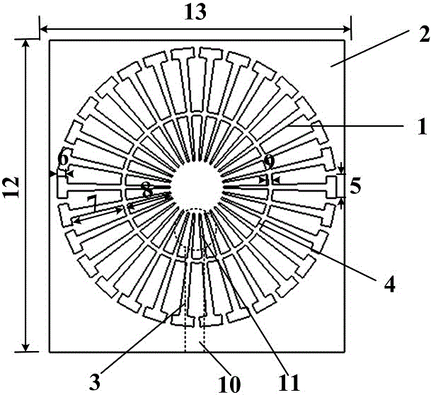
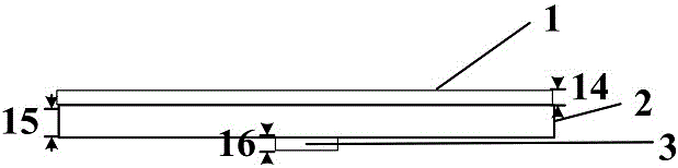
[0022] see figure 1 and figure 2 , a multi-frequency high-gain electrically small antenna based on surface plasmon metamaterials, which sequentially includes a metal ring grating 1, a dielectric layer 2 and a microstrip line metal patch 3 from top to bottom; the metal ring grating 1, The dielectric layer 2 and the microstrip metal patch 3 are attached to each other. The size of the antenna is sub-wavelength, which is one-fifth of the wavelength of the lowest operating frequency of the antenna.

[0023] Grooves uniformly distributed along the circumferential direction are etched on the metal ring grating 1, and are divided into two parts by the ring structure 4, the inner and outer grooves, wherein the inner groove is a straight groove, and the outer groove is composed of two sections of straight grooves. "T" structure.

[0024] The microstrip metal patch 3 is composed of a short metal patch 10 and a circular structure 11 placed at its end. The material of the dielectric l...

Embodiment 2

[0029] Multi-frequency high-gain electrically small antenna array based on surface plasmon metamaterials see Figure 5 , including two electrically small antennas based on surface plasmon metamaterials, a first array element 17 and a second array element 18 . The first array element 17 and the second array element 18 are placed in parallel, and the distance is far less than 0.5 wavelength. In this embodiment, the distance 19 between the first array element 17 and the second array element 18 is 25 mm, which is 0.07 wavelengths of the lowest operating frequency point.

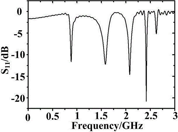
[0030] The structure pattern of the antenna array of the present invention is as follows Image 6 As shown, the maximum gain of (a) 900MHz antenna array is 3.6dB, (b) the maximum gain of 2.09GHz antenna array is 4.39dB, and (c) the maximum gain of 2.41GHz antenna array is 4.41dB.


PUM


Abstract

The invention discloses a surface plasmon meta-material based multi-frequency high-gain electric small antenna. The antenna comprises a metal annular grating, a dielectric layer and microstrip line metal patches, wherein the metal annular grating, the dielectric layer and the microstrip line metal patches are arranged successively from top to bottom and fit to one another. The size of the antenna is sub-wavelength which is about 1% of the wavelength, in the lowest working frequency, of the antenna. A surface plasmon meta-material based multi-frequency high-gain electric small antenna array comprises two or more a surface plasmon meta-material based multi-frequency high-gain electric small antennas, the unit spacing can be much lower than 0.5 wavelength, and the array gain is improved obviously. The antenna and antenna array have the advantages of small size, multiple frequency ranges, high gain and the like, the antenna and antenna array can work in multiple frequency ranges including the broadcast and television frequency range, the GSM frequency range and the WiFi frequency range, the gain and efficiency are higher, and the antenna and antenna array can be used for wireless energy collection.

Description

technical field [0001] The invention belongs to the field of microwave energy collection and microwave antennas, and relates to a multi-frequency high-gain electric small antenna and an array based on surface plasmon metamaterials. Background technique [0002] Collecting solar energy, vibration energy, wind energy, geothermal energy, tidal energy, etc. from the surrounding natural environment is highly dependent on the external environment and has high uncertainties, so it is not easy to control, which limits its use in some industries that require high reliability. applications, such as military and medical. In recent years, the Wireless Energy Harvesting (WEH) technology, which collects and stores energy from radio frequency (RF) signals in the surrounding environment, has become an international research hotspot. Due to the presence of a large number of radio frequency signals (such as mobile phone signals or Wi-Fi signals, etc.) in the natural environment, the energy o...

Claims


Application Information

Patent Timeline
Patent Type & Authority Applications(China)
IPC IPC(8): H01Q1/38H01Q21/06
CPCH01Q1/38H01Q21/067
Inventor 周永金杨柳
Owner SHANGHAI UNIV
Why Eureka
Try Eureka