Engine and braking mechanism thereof

A technology of braking mechanism and engine, applied in engine control, engine components, machine/engine, etc., can solve the problems of difficult layout and the space of the cylinder head occupied by the braking control structure.

Active Publication Date: 2016-12-14
WEICHAI POWER CO LTD
View PDF2 Cites 2 Cited by
  • Summary
  • Abstract
  • Description
  • Claims
  • Application Information

AI Technical Summary

Problems solved by technology

[0004] However, this type of structure is only suitable for the form of the camshaft overhead, and the brake control structure occupies the space of the cylinder head, so it is difficult to arrange

Method used


Image

  • Engine and braking mechanism thereof
  • Engine and braking mechanism thereof
  • Engine and braking mechanism thereof

Examples


Embodiment Construction

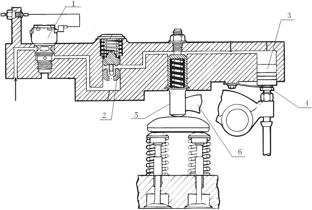
[0029] This embodiment provides a brake mechanism for an engine, which can be applied to a lower camshaft, does not occupy the space of a cylinder head, and is convenient to arrange. This specific embodiment also provides an engine including the above-mentioned braking mechanism.

[0030] Hereinafter, embodiments will be described with reference to the drawings. In addition, the embodiments shown below do not limit the content of the invention described in the claims in any way. In addition, all the contents of the configuration shown in the following embodiments are not limited to what is necessary as a solution to the invention described in the claims.

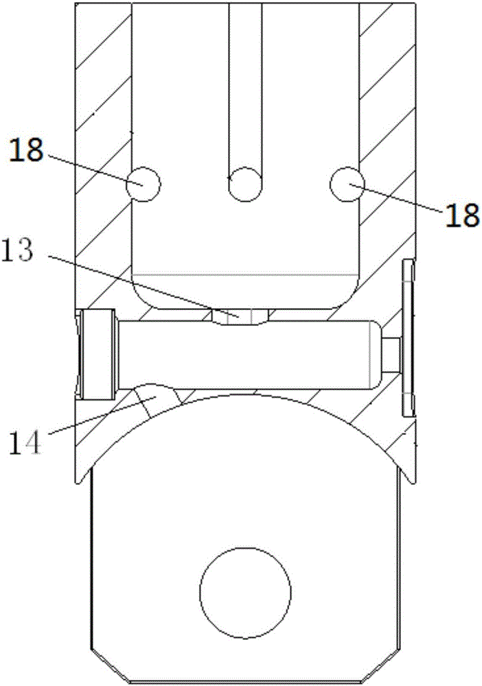
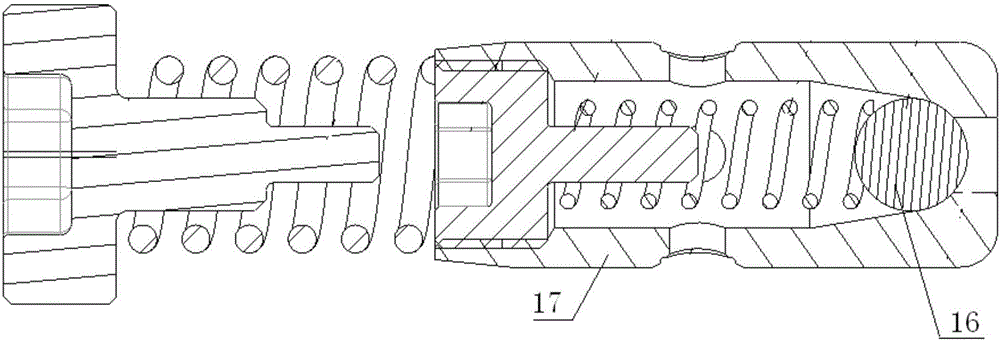
[0031] Please refer to Figure 2-Figure 6 The brake mechanism of an engine provided by this embodiment includes a camshaft, a tappet, a valve mechanism (not shown in the figure), and a first valve 16 and a second valve 17.

[0032] Among them, an exhaust cam 11 and a brake cam 12 are provided on the camshaft. When the camshaft r...


PUM


Abstract

The invention discloses an engine and a braking mechanism thereof. The braking mechanism comprises a cam shaft, a tappet, a gas distribution mechanism, a first valve and a second valve, wherein the tappet is driven by the cam shaft; the tappet is provided with a piston cavity, an oil supply pipeline and an oil leakage pipeline, the oil supply pipeline and the oil leakage pipeline communicate with the piston cavity, and a piston is arranged in the piston cavity; the gas distribution mechanism is used for controlling an exhaust valve to be opened or closed, and a braking gap is formed between the piston and the gas distribution mechanism; the first valve is used for controlling a braking oil duct to communicate with or separate from the oil supply pipeline; and the second valve is used for controlling the oil leakage pipeline to communicate with or separate from the outside. When braking is needed, oil is supplied in the braking oil duct, the first valve is controlled to be opened, the second valve is opened, when the piston moves to eliminate the braking gap, the first valve resets, the piston cavity forms a sealed cavity, accordingly, a braking cam drives the tappet to act, and the piston drives the gas distribution mechanism to act. Through the arrangement, the braking mechanism of the engine can be applicable to the under cam shaft, the space of a cylinder cover is not occupied, and arrangement is convenient.

Description

Technical field [0001] The present invention relates to the technical field of engines, and more specifically, to an engine and its braking mechanism. Background technique [0002] When the engine is braking, the nozzle stops fuel injection and controls the timing of opening the exhaust valve, turning the engine that was originally a power output device into an air compressor, which becomes a power consuming device. [0003] Please refer to figure 1 , figure 1 It is a schematic diagram of an engine braking mechanism in the prior art. When braking is required, voltage is applied to the brake control solenoid valve 1, the valve opens after the solenoid valve 1 is energized, and the oil flows into the control valve 2 along the oil passage. The control valve 2 moves up by the oil pressure, and the internal spherical check valve of the control valve Leaving the valve seat, the oil flows into the upper oil passage, the main piston 3 moves downwards under the action of oil pressure, and ...

Claims


Application Information

Patent Timeline
Patent Type & Authority Applications(China)
IPC IPC(8): F01L13/06F01L1/14F02D13/04
CPCF01L1/14F01L13/06F02D13/04
Inventor 张威
Owner WEICHAI POWER CO LTD
Why Eureka
Try Eureka