A multi-beam array galvanometer scanning system

A galvanometer scanning and multi-beam technology, applied in laser welding equipment, metal processing equipment, welding equipment, etc., can solve the problem of low scanning efficiency of single beam, achieve the effect of reducing processing time and cost, and increasing processing efficiency

Active Publication Date: 2019-01-29
SOUTH CHINA UNIV OF TECH
View PDF9 Cites 0 Cited by
  • Summary
  • Abstract
  • Description
  • Claims
  • Application Information

AI Technical Summary

Problems solved by technology

[0005] The main purpose of the present invention is to overcome the shortcomings and deficiencies of the prior art, and provide a multi-beam array galvanometer scanning system, which can realize the effect of multi-beam scanning without increasing the number of lasers, effectively solving the problem of single The problem of low beam scanning efficiency also has the advantages of simple structure and low cost

Method used


Image

  • A multi-beam array galvanometer scanning system
  • A multi-beam array galvanometer scanning system
  • A multi-beam array galvanometer scanning system

Examples


Embodiment

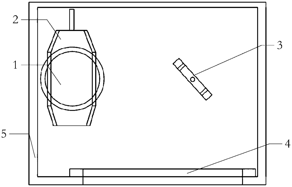
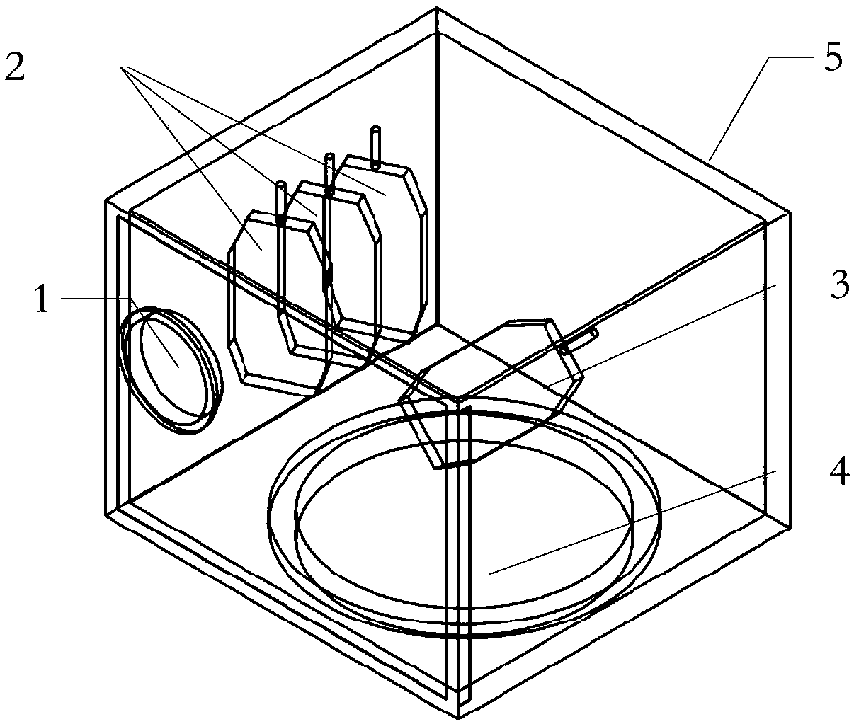
[0026] Such as Figures 1 to 4 As shown, a multi-beam array galvanometer scanning system designed in the present invention includes a light inlet 1, an X-axis array galvanometer system 2, a Y-axis galvanometer system 3, a light outlet 4, and a galvanometer frame structure 5. The mirror frame structure 5 is equipped with an X-axis array galvanometer system 2 and a Y-axis galvanometer system 3. The X-axis array galvanometer system 2 or the Y-axis galvanometer system 3 is composed of a plurality of galvanometers whose axes are parallel to each other. , the laser beam expanded by the beam expander enters the array galvanometer scanning system through the light inlet 1, and the beam reaches the X-axis array galvanometer system 2 or the Y-axis galvanometer system 3 and is divided into n parallel beams with the same light intensity , the parallel light beam passes through the light outlet 4 and is focused by the F-θ mirror onto the forming plane to form a group of n light spots. The...


PUM


Abstract

The invention discloses a multi-beam-array galvanometer scanning system. The multi-beam-array galvanometer scanning system comprises a galvanometer frame structure; the galvanometer frame structure is internally provided with an X-axis array galvanometer system and a Y-axis galvanometer system; the X-axis array galvanometer system or the Y-axis galvanometer system is composed of a plurality of galvanometers with parallel axis lines, lasers after beam expanding through a beam expander enters the multi-beam-array galvanometer scanning system through a laser inlet, beams arrive the X-axis array galvanometer system and are equally divided into n parallel beams with the same light intensity, the n parallel beams are driven by various X-axis galvanometers in a deflection manner to achieve any movement in the X direction, and are projected to the Y-axis galvanometer system, under the deflection reflection drive of Y-axis galvanometers, n sets of beams move in the Y direction, and finally, the n sets of beams pass through a beam outlet and are focused by an F-theta lens to a molding plane to form a set of spots with the number of n. Through the technical scheme, the machining efficiency can be increased in a multiplied manner, the number of multiplied numbers is the same with the number of galvanometer arrays, the machining time is greatly shortened, and the machining cost is greatly reduced.

Description

technical field [0001] The invention relates to a process of laser selective melting / sintering to form 3D parts, in particular to a multi-beam array galvanometer scanning system. Background technique [0002] The laser selective melting / sintering molding process is a processing process in which a certain power laser scans the molding plane and superimposes it layer by layer to form a solid body. The focused laser spot scans the metal powder on the molding plane with a preset path, and the metal or polymer powder scanned by the spot melts and condenses instantly to form a solid body, and then the molding plane drops to a certain height, and the powder is re-spread to form a new molding plane, the laser continues to scan on the new molding plane, and so on until the molding is finished. During the processing, the laser scanning path is controlled by the scanning galvanometer system, and the scanning effect of the galvanometer system will directly affect the final molding effe...

Claims


Application Information

Patent Timeline
Patent Type & Authority Patents(China)
IPC IPC(8): B23K26/06B23K26/067B23K26/082
CPCB23K26/0604B23K26/067B23K26/082
Inventor 宋长辉王安民杨永强王迪李阳
Owner SOUTH CHINA UNIV OF TECH
Why Eureka
Try Eureka