
Gate driving circuit applying SiC power tube for bridge type power converter

A technology of power converter and power tube, which is applied in the direction of output power conversion device, DC power input conversion to DC power output, high-efficiency power electronic conversion, etc. It can solve the problem of driving loss power and reliability reduction, excessive switching loss, Increased circuit power density and other issues to achieve the effect of reducing drive loss, improving reliability, and improving stability

Inactive Publication Date: 2016-12-07
SOUTHEAST UNIV
View PDF4 Cites 12 Cited by
  • Summary
  • Abstract
  • Description
  • Claims
  • Application Information

AI Technical Summary

Problems solved by technology

②The power density of the whole circuit is further increased
[0004] In recent years, many gate drive design schemes mainly focus on solving the problem of excessive switching loss. Although ZVS and ZCS soft switching technologies have been widely used in full-bridge converters, in practical applications, with the switching frequency As the increase, a large number of driving losses still exist and thus cause the phenomenon of reduced power and reliability

Method used


Image

  • Gate driving circuit applying SiC power tube for bridge type power converter
  • Gate driving circuit applying SiC power tube for bridge type power converter
  • Gate driving circuit applying SiC power tube for bridge type power converter

Examples


Embodiment Construction

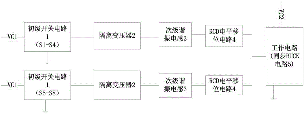
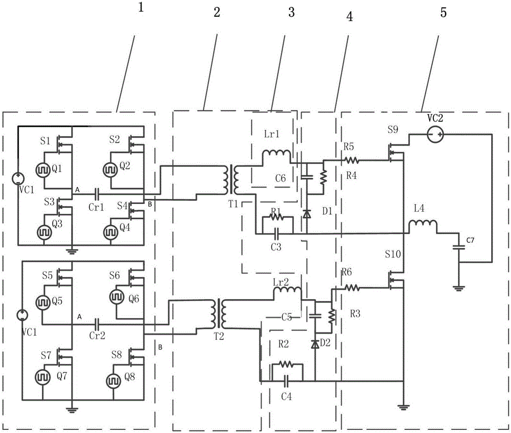
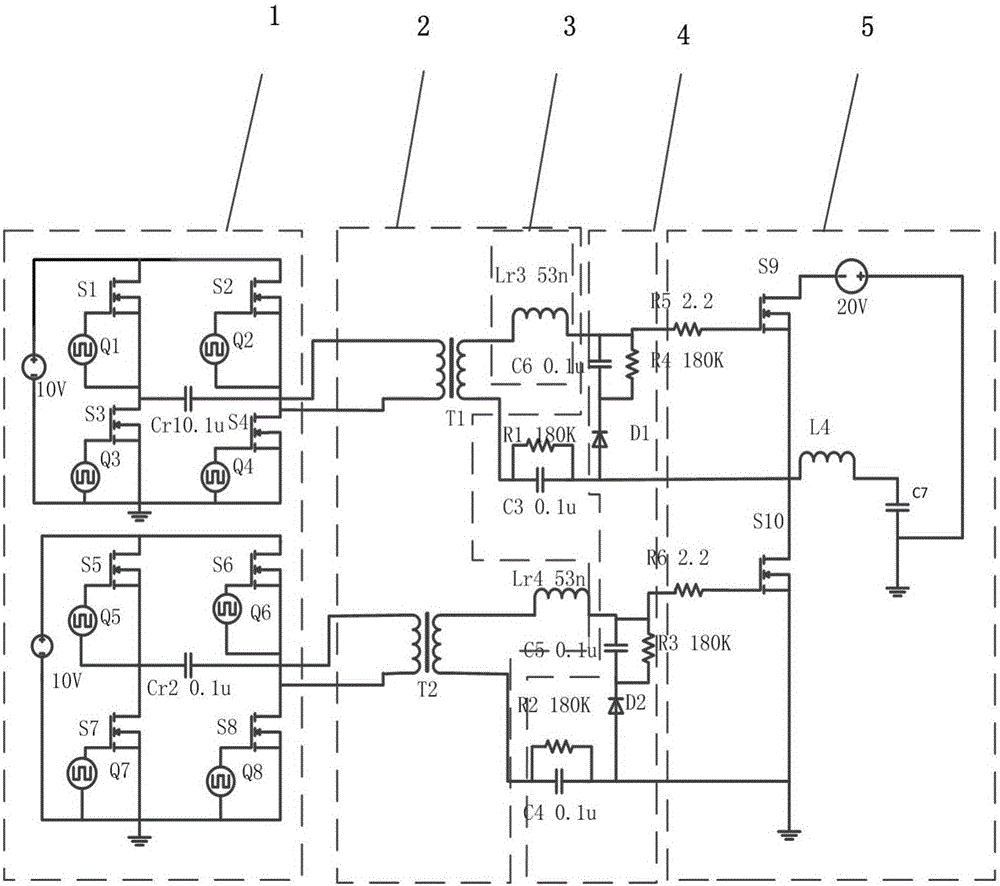
[0025] The technical solution of the invention will be described in detail below with reference to the embodiments given in the accompanying drawings. The bridge power converter in the embodiments uses a synchronous BUCK circuit, and the synchronous BUCK rectifier circuit is used as a half-bridge test carrier.

[0026]The synchronous BUCK circuit includes SiC power transistors S9 and S10 on the high and low voltage sides, voltage source VC2, inductor L4, output capacitor C7, and gate drive resistors R5 and R6. The drain of the SiC power transistor S9 on the high voltage side is connected to the negative pole of the voltage source VC2. The anode of the voltage source VC2 is connected to one end of the output capacitor C7 and grounded, and the other end of the output capacitor C7 is connected to the anode of the diode D1 in the first part of the RCD level shift circuit through the inductor L4 and the anode of the diode D1 is connected to the source of S9 and the source of S10 The...


PUM


Abstract

A gate driving circuit applying a SiC power tube for a bridge type power converter comprises two parts of circuits, wherein the two parts of circuits have same structures, each part of circuit comprises a primary switching circuit, an isolation transformer and a RCD level shift circuit, a traditional coupling isolation transformer is divided to discrete isolation transformers, secondary power tubes are respectively controlled and driven by discrete primary driving circuits, and secondary sides of the isolation transformers are respectively connected in series with a resonant inductor and a level shift circuit. By the gate driving circuit, the driving loss of the resonant gate driving circuit can be greatly reduced, the probability of misconduction of the SiC power tube is reduced, meanwhile, the probability of straight through of an upper tube and a lower tube of the SiC power tube is reduced, and the gate driving circuit is high in reliability and high in efficiency.

Description

technical field [0001] The invention relates to a gate drive circuit of a bridge power converter, in particular to a gate drive circuit of a bridge power converter using a SiC power tube (SiC metal-oxide semiconductor field effect transistor). Background technique [0002] At present, the switching frequency in the power converter is getting higher and higher, and the advantages brought by the increase of the switching frequency are as follows: ① The volume of the energy storage device (inductor, transformer, capacitor, etc.) in the circuit is correspondingly reduced. ②The power density of the whole circuit is further increased. But the increase of switching frequency also brings the increase of switching loss. For the gate drive circuit, it is not only necessary to solve the problem of increased switching loss due to the increase of the switching frequency, but also to solve the related problems related to the false conduction and straight-through of the secondary SiC MOSF...

Claims


Application Information

Patent Timeline
Patent Type & Authority Applications(China)
IPC IPC(8): H02M3/335
CPCH02M3/3353H02M3/33561Y02B70/10
Inventor 孙伟锋夏熙朱俊杰刘鹏钱钦松陆生礼时龙兴
Owner SOUTHEAST UNIV
Learn More