Synchronous rectification self-excitation drive circuit and method for disconnector converter

A technology of synchronous rectification and isolation switch, which is applied in conversion devices and instruments for converting DC power input into DC power output and output power, etc., can solve the problems of increasing driving loss, reducing the efficiency and working reliability of the converter, etc. Achieve the effect of reducing drive loss, improving efficiency and working reliability, and good versatility

Active Publication Date: 2012-01-18
SHENZHEN VAPEL POWER SUPPLY TECH
View PDF0 Cites 4 Cited by
  • Summary
  • Abstract
  • Description
  • Claims
  • Application Information

AI Technical Summary

Problems solved by technology

However, this driving method oscillates due to the auxiliary winding coupling leakage inductance and the gate junction capacitance of the MOS transistor, causing the rising edge and flat top part of the driving waveform to oscillate (see e.g. Figure 4 drive waveform shown), resulting in increased drive loss
Therefore, the oscillating driving voltage waveform formed by the auxiliary winding coupling magnetic circuit leakage inductance and the gate junction capacitance of the MOS tube greatly reduces the efficiency and reliability of the converter.

Method used


Image

  • Synchronous rectification self-excitation drive circuit and method for disconnector converter
  • Synchronous rectification self-excitation drive circuit and method for disconnector converter
  • Synchronous rectification self-excitation drive circuit and method for disconnector converter

Examples


Embodiment Construction

[0027] The present invention will be further described in detail below through embodiments in conjunction with the accompanying drawings.

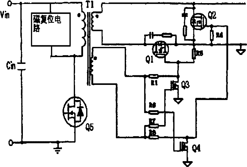
[0028] Such as Figure 5 As shown, according to the embodiment of the present invention, the isolated switching converter includes a transformer, a synchronous rectification MOS transistor Q5, a synchronous freewheeling MOS transistor Q6, and a synchronous rectification self-driver that provides drive signals to the synchronous rectification MOS transistor and the synchronous freewheeling MOS transistor. circuit. The transformer has a main primary winding on the primary side, a main secondary winding and an auxiliary driving winding on the secondary side. The synchronous rectification self-driving circuit includes an auxiliary driving winding and a shaping interlock unit. The auxiliary driving winding is coupled to the synchronous rectification MOS transistor through the shaping interlocking unit. and the gate of the synchronous freewheel...


PUM


Abstract

The invention discloses a synchronous rectification self-excitation drive circuit for a disconnector converter, comprising a transformer secondary auxiliary driving winding. The auxiliary driving winding supplies gate driving voltage to a synchronous rectification MOS transistor and a synchronous freewheeling MOS transistor of the disconnector converter; the circuit further comprises a shaping interlocking unit; the auxiliary driving winding is coupled with gates of the synchronous rectification MOS transistor and the synchronous freewheeling MOS transistor through the shaping interlocking unit, and the shaping interlocking unit applies positive voltage supplied by the auxiliary driving winding to the gates of the synchronous rectification MOS transistor during the rectification stage of the entire switching period and clamps the gate voltage of the synchronous freewheeling transistor to zero, and applies positive voltage supplied by the auxiliary driving winding to the gates of the synchronous freewheeling MOS transistor during the freewheeling stage of the entire switching period and clamps the gate voltage of the synchronous rectification transistor to zero. The invention further discloses a corresponding synchronous rectification self-excitation drive method. The synchronous rectification self-excitation drive circuit and the method can reduce the drive loss and improve the efficiency and the working reliability of the converter.

Description

technical field [0001] The invention relates to a synchronous rectification technology of a switch converter, in particular to a synchronous rectification self-excitation drive circuit and method for an isolated switch converter. Background technique [0002] In switching converter technology, synchronous rectification technology is an important technology for low-voltage and high-current switching converters. It can greatly improve the efficiency of switching converters, and there is no dead zone voltage caused by Schottky barrier voltage. Power MOSFET (Metal Oxide Semiconductor Field Effect Transistor, referred to as MOS tube) is a voltage-controlled device, and its volt-ampere characteristic is linear when it is turned on. When using a power MOSFET as a rectifier tube, it is required that the gate voltage must be the same as the rectified The rectification function can only be completed when the phase of the voltage is kept synchronous, so it is called synchronous rectifi...

Claims


Application Information

Patent Timeline
Patent Type & Authority Patents(China)
IPC IPC(8): H02M3/335
CPCY02B70/1475Y02B70/10
Inventor 钟启豪李战伟刘取仁江申才
Owner SHENZHEN VAPEL POWER SUPPLY TECH
Why Eureka
Try Eureka