
Field runoff and sediment automatic monitoring equipment and monitoring method

An automatic monitoring and runoff technology, applied in the direction of measuring devices, material weighing, instruments, etc., can solve the problems of large measurement errors, difficult power supply, uneven distribution, etc., achieve low production and maintenance costs, simple and reliable design structure, and calculation methods simple effect

Inactive Publication Date: 2018-12-28
长江水利委员会长江流域水土保持监测中心站
View PDF6 Cites 0 Cited by
  • Summary
  • Abstract
  • Description
  • Claims
  • Application Information

AI Technical Summary

Problems solved by technology

The runoff and sediment automatic monitoring equipment designed based on the indirect derivation method is often limited by many conditions, such as power conditions, maintenance management, cost, etc. These runoff and sediment automatic monitoring equipment are often used in laboratories or areas with high management levels. It is more difficult to promote the application in the wild
[0003] The automatic runoff sediment monitoring equipment designed based on the direct measurement method is mainly limited by the measurement accuracy and automation level. For example, the current automatic runoff sediment monitoring equipment designed by the specific gravity method uses a large number of small runoff bottles or weighing bottles as carrying tools. The measurement error is large, and it is very easy to silt, which is not easy to manage and maintain; at the same time, most of the runoff and sediment automatic monitoring equipment needs stirring or pumping equipment, which puts forward higher requirements for power supply, which also limits its use in remote areas. Applications
[0004] For example, patent 201510121355.0 is based on two siphon-type water inlets for mixing, and uses a small weighing bottle for weighing. This kind of equipment is prone to sedimentation, and there are certain restrictions on maintenance and management; patent 201410232617.6 uses motor drive, which can automatically sample and measure Multi-layer runoff and sediment volume, but the measurement of sediment volume needs to stop water inflow, and the degree of automation of sediment determination is low, which limits its use in the field. Patent 201520151152.1 uses three siphon devices to enter the weighing bottle, and The cantilever beam load cell is used for weighing, and the impeller is used to count and calculate the flow rate. The structure is limited by the size of the weighing bottle and cannot reduce the impact of the water flow impulse load cell. There is a certain error. When unattended, limited reliability
[0005] To sum up, so far, the equipment design for automatic monitoring of soil erosion, runoff and sediment in the field has the following technical problems: (1) The field environment is harsh, unattended, the equipment structure is complex and difficult to maintain, the service life is short, the degree of automation is low, and the accuracy is low. (2) Motors or motors are required, high energy consumption, difficult power supply, and increased manufacturing costs; (3) The runoff is unevenly distributed when it enters the cylinder from the inlet, impacting the liquid surface, resulting in water level signals and weight signals Inaccurate collection
(4) The equipment is easy to deposit sediment, and it becomes a problem to fully empty the sediment after completing a phased monitoring, which reduces the accuracy of the next measurement
(5) Since it is unattended, the equipment must adapt to the requirements of field operations and meet the functions of full automatic operation, analysis and transmission

Method used


Image

  • Field runoff and sediment automatic monitoring equipment and monitoring method
  • Field runoff and sediment automatic monitoring equipment and monitoring method
  • Field runoff and sediment automatic monitoring equipment and monitoring method

Examples


Embodiment 1

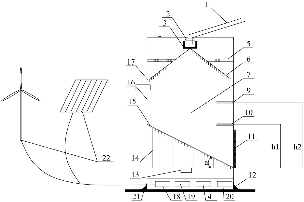
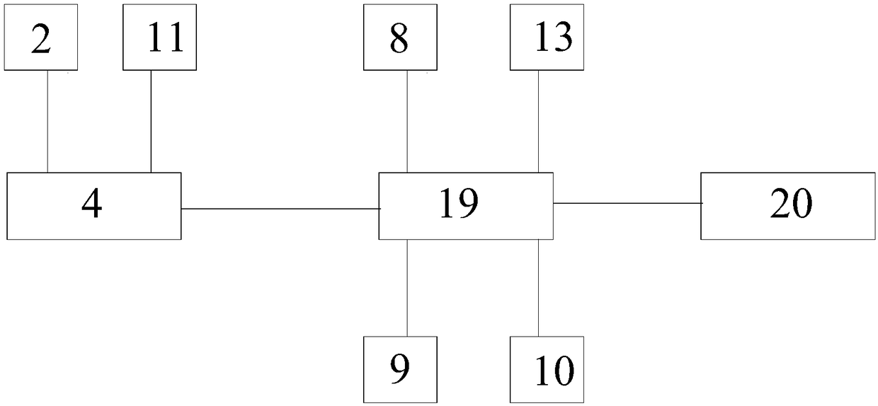
[0040] 1) When it rains, the single-chip microcomputer 19 controls the water inlet electromagnetic valve 2 to open through the electromagnetic valve controller 4, and the water outlet electromagnetic valve 11 closes, and the runoff flows into the concave overflow tank 3 through the runoff inlet pipe 1, and the concave overflow tank 3 can weaken the direct impact force of the runoff , and can disperse the sediment in the runoff. The runoff overflows with the concave overflow tank 3 and then is filtered by the support filter 5 and then flows to the upper surface of the conical water guide plate 6. After the runoff is evenly distributed by the conical water guide plate 6, it passes through the gap 17 flows into the storage chamber 7 along the side wall of the cylinder 16, so that the incoming water avoids directly impacting the liquid surface, and the elapsed time t 1 When the water level reaches the lower water level probe 10, the water level probe 10 sends a signal to the single...

Embodiment 2

[0045] Step (1) is the same as the monitoring process embodiment 1, the difference is that when the water level reaches the lower water level probe 10, the water will continue to flow in until the water level passes the time t 2 When reaching the upper water level probe 9, the load cell 13 records and sends the information into the single-chip microcomputer 19 to store it as the weight M 2 , timer 8 records time t 2 And the information is transferred to the single-chip microcomputer 19 and stored as t 2 , the single-chip microcomputer 19 and the electromagnetic valve control unit 4 control the water inlet electromagnetic valve 2 to close, and the water outlet electromagnetic valve 11 to open, so that the liquid in the flow storage chamber 7 can be quickly discharged;

[0046] In step (2), carry out following data processing in single-chip microcomputer 19: combine the height of known lower water level probe 10 i.e. low water level h 1 , The height of the upper water level pr...


PUM


Abstract

The invention relates to automatic field runoff sediment monitoring equipment and an automatic field runoff sediment monitoring method. The automatic field runoff sediment monitoring equipment comprises a barrel, a water inlet valve connected with a runoff water inlet pipe is arranged at the top of the barrel, a sediment storage chamber is arranged in the middle of the barrel, a water outlet valve is arranged in the bottom side wall of the barrel, and a tapered water guide plate is arranged under the water inlet valve; the bottom surface of the sediment storage chamber is provided with a sloped water storage base plate supported on the bottom surface of the barrel through a support structure, and the lowest end of the sloped water storage base plate corresponds to the lower end of the water outlet valve; at least one water level probe is arranged on the side wall of the barrel, and the height of the water level probe at the lowest position aligns to the highest end of the sloped water storage base plate; a weighing sensor is arranged on the bottom surface of the barrel. The automatic field runoff sediment monitoring method is further adopted. The automatic field runoff sediment monitoring equipment is simple and reliable in structure, easy to operate, low in energy consumption, high in automation degree, good in sediment discharging, high in accuracy and low in production and maintenance cost. The method is simple, reliable, simple in calculation, high in accuracy and high in operability.

Description

technical field [0001] The invention discloses an automatic monitoring device and a monitoring method for runoff sediment, in particular to an automatic monitoring device and a monitoring method for runoff sediment in the field. Background technique [0002] The runoff sediment concentration in soil erosion is one of the important parameters to measure soil erosion, and it is also the main content of soil and water conservation monitoring. According to different measurement principles, sediment measurement methods can be divided into: direct measurement method and indirect derivation method. The runoff and sediment automatic monitoring equipment designed based on the indirect derivation method is often limited by many conditions, such as power conditions, maintenance management, cost, etc. These runoff and sediment automatic monitoring equipment are often used in laboratories or areas with high management levels. It is more difficult to promote and apply in the wild. [00...

Claims


Application Information

Patent Timeline
Patent Type & Authority Patents(China)
IPC IPC(8): G01N5/00
CPCG01N5/00
Inventor 邹汝良李仁华姚赫江宁张勇项宇
Owner 长江水利委员会长江流域水土保持监测中心站
Learn More