
Gear transmission device of GTF engine

A gear transmission and gear drive technology, applied in the direction of gear transmission, transmission, transmission parts, etc., to achieve the effect of increasing flexibility and radial floating effect, and ensuring radial floating and equalizing effect.

Active Publication Date: 2016-12-07
CHONGQING UNIV +1
View PDF4 Cites 9 Cited by
  • Summary
  • Abstract
  • Description
  • Claims
  • Application Information

AI Technical Summary

Problems solved by technology

[0008] In order to solve the problem of positioning accuracy of parts assembly in the existing gear drive fan (GTF) engine gear transmission system, the present invention proposes a gear drive fan (GTF) engine gear transmission device. The word sun gear has a simple structure and is easy to disassemble and replace. It can meet the requirements of processing and assembly technology, greatly improve the assembly accuracy, meet the actual needs of enterprises, and fill the gaps in related technologies.

Method used


Image

  • Gear transmission device of GTF engine
  • Gear transmission device of GTF engine
  • Gear transmission device of GTF engine

Examples


Embodiment Construction

[0033] The present invention will be further described below in conjunction with embodiments, but it should not be understood that the scope of the above subject matter of the present invention is limited to the following embodiments. Without departing from the above-mentioned technical idea of ​​the present invention, various substitutions and changes based on common technical knowledge and conventional means in the field shall be included in the protection scope of the present invention.

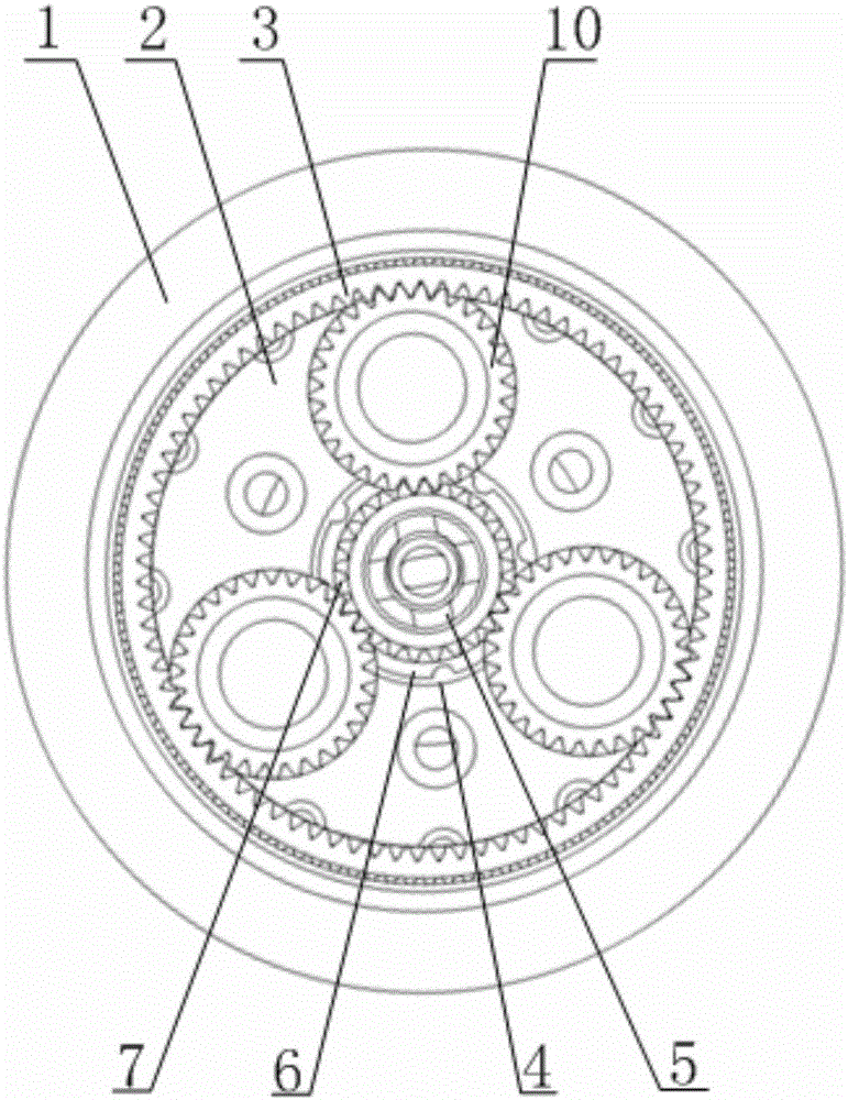
[0034] See figure 1 , A gear driven fan (GTF) engine gear transmission device, which mainly includes: planet carrier cover 1, planet carrier 2, herringbone ring gear 3, input spline sleeve 4, sun gear fixing nut 5, sun gear A6, sun Gear B7, planetary shaft 8, planetary shaft fixing nut 9, herringbone planetary gear 10, herringbone planetary gear bearing 11, transmission shaft 12, fan sleeve 13, cylindrical roller bearing 14 and radial ball bearing 15.

[0035] See figure 2 , A number of the he...


PUM


Abstract

The invention relates to a gear transmission device of a GTF engine. The gear transmission device comprises a fan sleeve, an inverted-V-shaped inner gear ring, inverted-V-shaped planet gears, a planet carrier, an input spline sleeve, two sun gears, a transmission shaft and the like. The sun gears conduct input, the planet gears only conduct self-rotation, and the inverted-V-shaped inner gear ring conducts output. The inverted-V-shaped inner gear ring is connected with the transmission shaft, the transmission shaft is connected with the fan sleeve through a spline, and the fan sleeve serves as the output end to be connected with the fan so as to achieve the deceleration and torque increasing movement. The rotation speed ratio of the fan sleeve to the input spline sleeve is equal to the gear ratio of the sun gears to the inverted-V-shaped inner gear ring. According to the gear transmission device, the rotation speed of a fan rotor is reduced, the fan and a low-pressure turbine do not need to work at the same rotating speed, the fan works at the low rotating speed when pneumatic losses and noise are low, and therefore the bypass ratio of the engine is increased. Meanwhile, a low-pressure rotor can work at the high rotation speed with high efficiency, so that the high rotation speed of the low-pressure rotor is matched with the optimal rotation speed of a high-pressure rotor, and the engine has the beneficial effects of being low in noise, emission and oil consumption rate and the like.

Description

Technical field [0001] The present invention relates to the technical field of gear transmission, in particular to a gear drive fan (GTF) engine gear transmission device. Background technique [0002] Reducing fuel consumption and reducing pollution emissions are the main development directions of the next generation of civil aviation engines. The Geared Turbofan Engine (GTF) engine has the advantages of low emissions, low noise, low fuel consumption and low maintenance costs. [0003] At present, in large-thrust (greater than 70.00kN) high bypass ratio turbofan engines, the fans are directly driven by low-pressure turbines; generally 3-5 stage supercharged compressors (sometimes called low-pressure compressors) are installed behind the fan rotor. In order to increase the total pressure ratio of the engine and the internal air flow. But this design has inherent shortcomings, that is, the supercharged compressor and low-pressure turbine do not work at their optimal speeds, which i...

Claims


Application Information

Patent Timeline
Patent Type & Authority Applications(China)
IPC IPC(8): F16H1/32F16H57/023F16H57/021
CPCF16H1/32F16H57/021F16H57/023F16H2001/327
Inventor 魏静白培鑫张鸿
Owner CHONGQING UNIV
Learn More