Construction equipment for concrete piles and construction method of construction equipment

A kind of construction equipment and concrete pile technology, which is applied in the direction of sheet pile wall, foundation structure engineering, construction, etc., can solve the problems that it is difficult to form the design depth of the pile hole, the original soil is not fully utilized, and the next step of construction cannot be carried out, etc., to achieve Reduce the link of soil clearing and transportation, wide application range and enhanced strength

Inactive Publication Date: 2016-12-07
王继忠 +2
View PDF6 Cites 2 Cited by
  • Summary
  • Abstract
  • Description
  • Claims
  • Application Information

AI Technical Summary

Problems solved by technology

This geological condition makes it very difficult to form holes in the pile body during pile foundation construction. At present, the commonly used methods such as vibration sinking, static pressure or rotary drilling are basically difficult to form pile holes to the design depth.
Although some construction methods such as rotary drilling rigs and manual digging can form holes in these harder soil layers, the cost of construction is relatively high and the speed is slow, and they are all methods of taking out the original soil in the foundation. The need to clear the soil and transport it increases the cost and is easy to pollute the environment. The original soil is not fully utilized and there is no pile hole wall, which can easily cause the hole wall to collapse and shrink. Especially when the groundwater content is high, the pile hole will quickly water, unable to carry out the next step of construction

Method used


Image

  • Construction equipment for concrete piles and construction method of construction equipment
  • Construction equipment for concrete piles and construction method of construction equipment
  • Construction equipment for concrete piles and construction method of construction equipment

Examples


Embodiment Construction

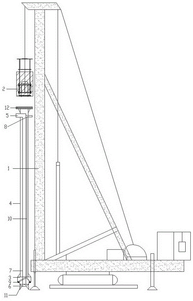
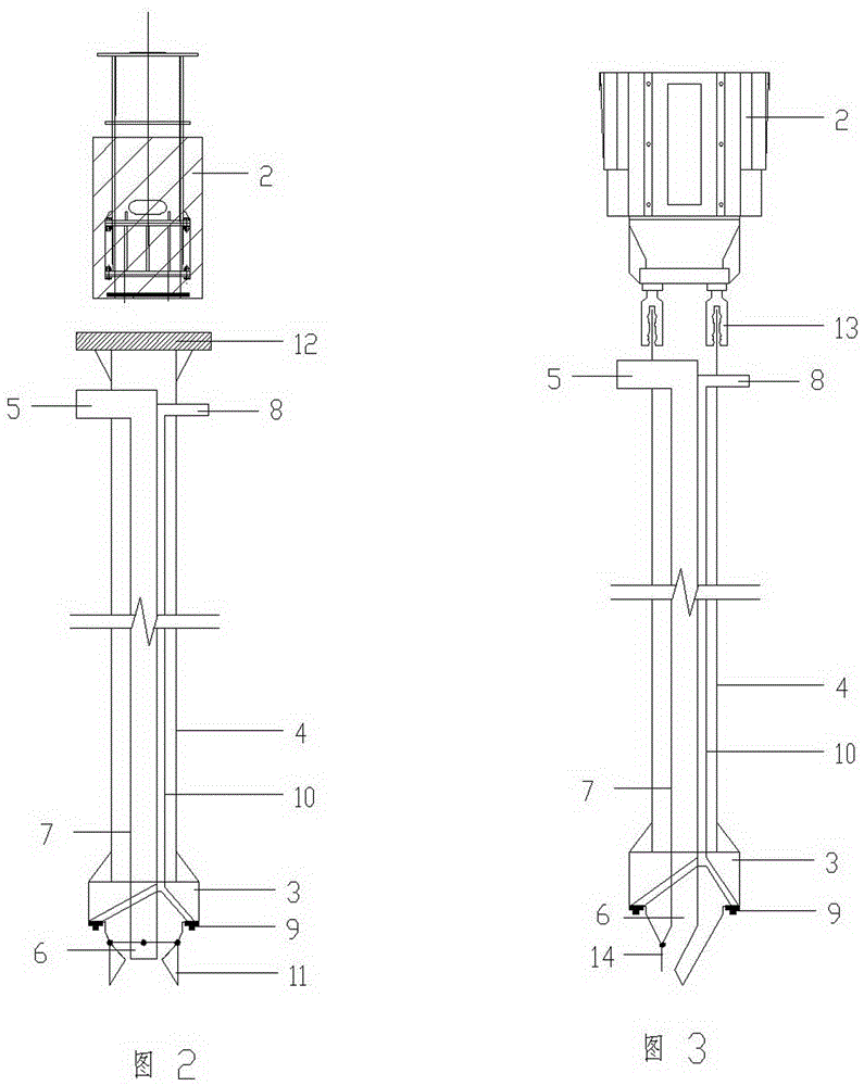
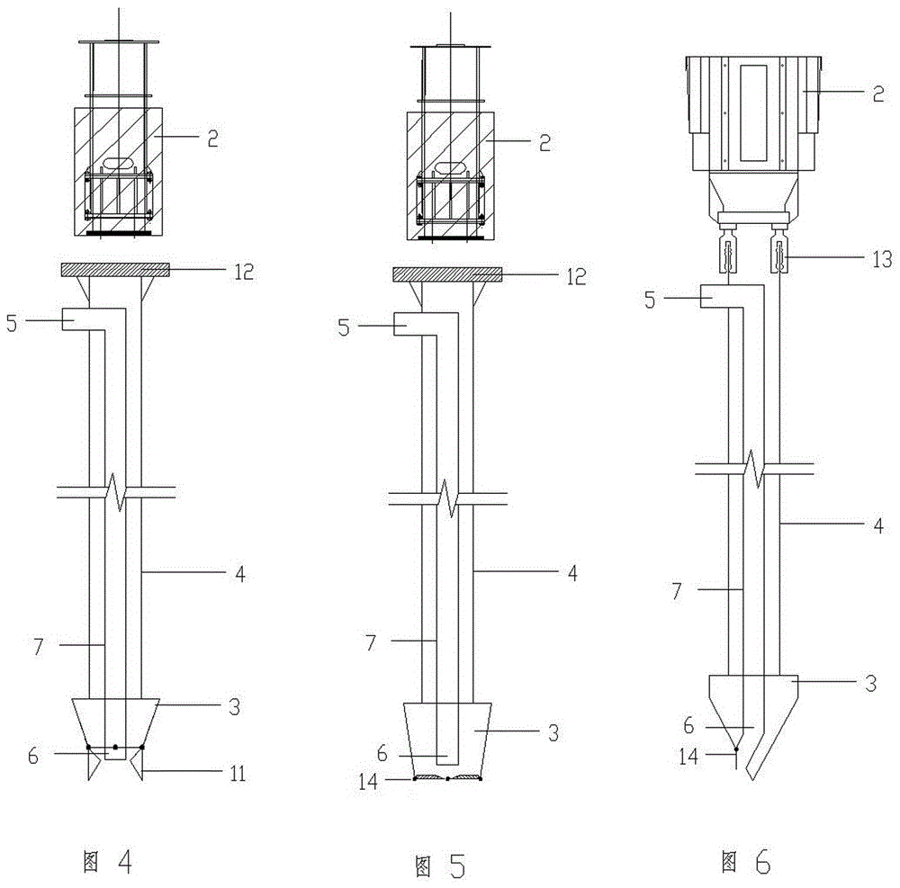
[0029] figure 1 It is a schematic diagram of a preferred embodiment of the construction equipment of the concrete pile of the present invention, as figure 1 As shown, the construction equipment includes a frame 1, a power hammer 2, and a stamping device. The frame 1 adopts a long auger drill. 2. Diesel hammer is used. The stamping device is located under the power hammer (2) and can move up and down along the vertical rod. The stamping device includes impact hammer head 3, hollow rod 4, feeding device, and grouting device; impact hammer head 3 is fixed At the bottom of the hollow rod 4, the lower part of the impact hammer 3 has a valve tip 11 that can be opened and closed; the diameter of the hollow rod 4 is smaller than that of the impact hammer 3, and the top of the hollow rod 4 is provided with a rammer. The striking plate 12 is convenient for the impact of the power hammer 2; the feeding device includes a feeding pipe 7 with a feeding port 5 and a feeding port 6, and the ...


PUM


Abstract

The invention provides construction equipment for concrete piles. The construction equipment comprises a rack, a power hammer and a stamping device, and is characterized in that the power hammer is arranged on an upright of the rack; the stamping device is arranged under the power hammer, and comprises an impact hammer, a hollow rod, a material conveying device and a grouting device, or the impact hammer, the hollow rod and the material conveying device, or the impact hammer, the hollow rod, the material conveying device, the grouting device and a diameter expanding part additionally arranged at the upper end of the hollow rod. The invention further provides a construction method which comprises the following steps: 1) aligning with a pile position; 2) beating the stamping device with the power hammer, so that soil is impacted downwards, extruded and expanded; 3) impacting and lubricating the soil with a high-pressure jet if the grouting device is available, or directly repeating the impacting operation if the grouting device is unavailable; 4) forming a pile hole when a set depth is reached, for example, the diameter expanding part forms an expanded diameter naturally; 5) when lifting the stamping device, conveying concrete in a pressurized manner, and pouring the concrete into the pipe hole; 6) lifting the stamping device out of the soil to form a concrete pile; and 7) inserting a reinforcing cage reversely when the construction method is used for formation of a pile foundation, and laying a cushion layer at the top of the pile when the construction method is used for formation of a composite foundation.

Description

technical field [0001] The present application relates to the field of civil engineering, in particular to construction equipment for concrete piles and a construction method for concrete piles. Background technique [0002] At present, in the foundation treatment engineering in the field of construction engineering, such a situation is often encountered: there are dense sandy soil layers, gravel soil layers, loess layers, gravel and pebble layers, etc. at a certain depth below the surface, and these soil layers Uneven hardness and uneven thickness. This geological condition makes it very difficult to form holes in the pile body during pile foundation construction. At present, it is difficult to form pile holes to the designed depth with the commonly used methods such as vibratory sinking, static pressure or rotary drilling. Although some construction methods such as rotary drilling rigs and manual digging can form holes in these harder soil layers, the cost of construction...

Claims


Application Information

Patent Timeline
Patent Type & Authority Applications(China)
IPC IPC(8): E02D7/10E02D15/04
CPCE02D7/10E02D15/04
Inventor 王继忠张连喜王光亮
Owner 王继忠
Why Eureka
Try Eureka