
Installation method for blast furnace bottom water cooling beam and blast furnace bottom water cooling pipe

An installation method and technology of water-cooled beams, which are applied to cooling devices and other directions, can solve problems such as poor construction conditions on site, difficulty in reinforcement, and heavy workload, and achieve the effects of ensuring manufacturing quality, reducing construction procedures, and small welding volume

Active Publication Date: 2016-12-07
CHINA 19TH METALLURGICAL CORP
View PDF4 Cites 0 Cited by
  • Summary
  • Abstract
  • Description
  • Claims
  • Application Information

AI Technical Summary

Problems solved by technology

[0004] 1. Water-cooled beams and water-cooled pipes are installed in loose parts, and there are many specifications and models of components. It is difficult to clean the components on site, and it is easy to mix components with similar specifications and lengths;
[0005] 2. It is installed in loose parts, and the on-site installation workload is heavy. Due to the conditions of the blast furnace foundation cap on site, it is not easy to reinforce the components after installation, which may easily lead to welding deformation;
[0006] 3. Poor construction conditions on site are not conducive to controlling the installation accuracy of parts and poor quality;
[0007] 4. Stainless steel or carbon steel water cooling tubes are not easy to protect during the welding process, which may easily cause the water cooling tubes to be damaged during the welding process

Method used


Image

  • Installation method for blast furnace bottom water cooling beam and blast furnace bottom water cooling pipe

Examples


Embodiment Construction

[0025] The present invention will be further described below in conjunction with the accompanying drawings and embodiments.

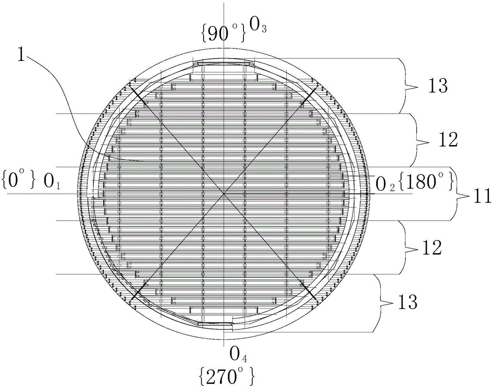
[0026] Such as figure 1 Shown, the blast furnace bottom water-cooled beam of the present invention and the installation method of water-cooled pipe comprise the following steps:

[0027] 1) According to the design drawings, the bottom water-cooled beam and water-cooled tube assembly 1 is aligned along the 0°-180° axis O 1 o 2 In the parallel direction, it is divided into five splicing blocks, and the five splicing blocks include splicing block one 11, two splicing blocks two 12 and two splicing blocks three 13;

[0028] The two splicing blocks 12 are respectively located on both sides of the splicing block one 11, and the two splicing blocks 12 are located between the splicing block one 11 and the splicing block 13; the two splicing blocks two 12 and the two splicing blocks 13 are about the axis O 1 o 2 Symmetry; the first splicing block 11, the se...


PUM


Abstract

The invention discloses an installation method for a blast furnace bottom water cooling beam and a blast furnace bottom water cooling pipe. According to the installation method, field construction processes are reduced, and the installation quality is improved. The installation method includes the steps that firstly, a furnace bottom water cooling beam and water cooling pipe assembling body is totally cut into five splicing blocks according to a design drawing; secondly, the five splicing blocks are produced in a factory; thirdly, the five splicing blocks are generally assembled on a factor splicing platform, and an installation coordinate system and a blast furnace center are marked on the furnace bottom water cooling beam and the furnace bottom water cooling pipe which are assembled; fourthly, a part is transported to the field; fifthly, the installation coordinate system and the blast furnace center of the furnace bottom water cooling beam and the furnace bottom water cooling pipe are discharged out on a blast furnace foundation bearing table through a total station; sixthly, the first splicing block, the second splicing blocks and the third splicing blocks are sequentially installed and spliced; and seventhly, after various items of installation sizes are checked to be qualified, welding is conducted. By the adoption of the installation method for the blast furnace bottom water cooling beam and the blast furnace bottom water cooling pipe, field construction process links are few, and safety and reliability are achieved; the installation precision is high, and quality is good; and the installation time is short, and the construction period is shortened.

Description

technical field [0001] The invention relates to the installation of water-cooled beams and water-cooled pipes at the bottom of a blast furnace, in particular to a method for installing the water-cooled beams and water-cooled pipes at the bottom of a blast furnace. Background technique [0002] Known: the bottom water cooling pipe of the blast furnace body system is used for circulating water cooling of the blast furnace bottom, and the heat transferred from the high temperature resistant carbon brick at the bottom of the blast furnace to the furnace bottom structure is transmitted through circulating water to ensure that the furnace bottom structure is at a safe temperature. The water cooling pipe adopts The water-cooled beams are fixed, and the weight of the blast furnace body structure is transferred to the blast furnace foundation through the water-cooled beams. The traditional furnace bottom water-cooled beams and water-cooled tubes are installed in bulk, that is, the wa...

Claims


Application Information

Patent Timeline
IPC IPC(8): C21B7/10
CPCC21B7/106
Inventor 蒋双全郭建华李进王凯肖健
Owner CHINA 19TH METALLURGICAL CORP
Learn More