
Forming mold and method for composite material pipe fitting

A composite material and molding die technology, which is applied to household appliances, tubular items, other household appliances, etc., can solve the problems of high mold processing cost, high product production cost, complex molding process, etc., to ensure the uniformity of wall thickness, reduce Equipment investment, good product quality and stability

Inactive Publication Date: 2016-12-07
SHANGHAI COMPOSITES SCI & TECH CO LTD
View PDF5 Cites 18 Cited by
  • Summary
  • Abstract
  • Description
  • Claims
  • Application Information

AI Technical Summary

Problems solved by technology

The present invention uses the core material layer covered with nylon bag film on the surface as the core mold of the forming mold, and implements internal pressure expansion molding, which effectively solves the complex molding process of existing composite material pipe fittings, high requirements for equipment, high mold processing costs, and product production. Inadequacies such as high cost and poor internal quality

Method used


Image

  • Forming mold and method for composite material pipe fitting
  • Forming mold and method for composite material pipe fitting

Examples


Embodiment 1

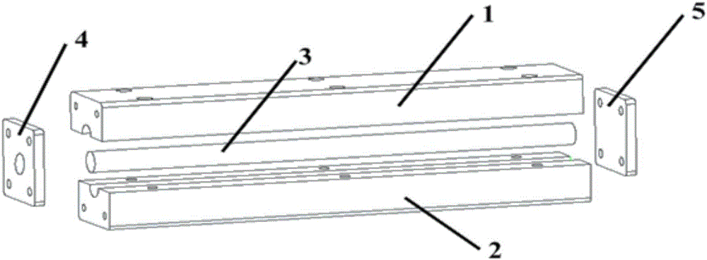
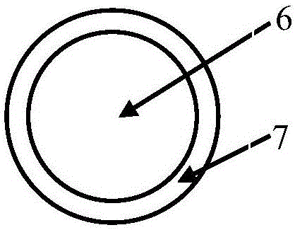
[0036] This embodiment provides a molding die for composite pipe fittings, such as figure 1 and figure 2 As shown, it includes a metal outer mold, a core mold 3 and a connection structure arranged at two ends of the metal outer mold; a through hole is arranged in the middle of the metal outer mold, and the core mold is arranged in the through hole; the metal outer mold is composed of an upper metal outer mold. The mold 1 and the lower metal outer mold 2 are composed; the core mold includes a core material layer 6 and a nylon bag film layer 7 sleeved on the outer surface of the core material layer.

[0037] The nylon bag film layer 7 is a bag film with a tubular structure, one end is sealed, and the other end is connected to an inflation nozzle.

[0038] The thickness of the bag film is 0.03mm-0.15mm, the elongation rate is not lower than 150%, the temperature resistance is not lower than 80°C, and the pressure resistance is not lower than 5MPa.

[0039] The core material la...

Embodiment 2

[0058] This embodiment provides a molding die and molding method for a composite material pipe fitting. The difference from Example 1 is that the cross-sectional shape of the prepared composite material pipe fitting is pentagonal, and the prepared polystyrene foam core material layer The cross-sectional shape is also pentagonal, and other mold structures, mold forming steps and parameters are the same as in Example 1. The wall thickness of the obtained composite pentagonal pipe fitting is 2mm (0mm, -0.05mm), and the flaw detection meets the requirements of Class A in GB2895.

[0059] To sum up, in order to meet the high-quality and low-cost application requirements of composite pipe fittings in high-tech fields such as aerospace, national defense, industry, and high-end sports, the present invention has gone through a lot of experiments and used nylon bag film to cover polystyrene foam The core mold 3 is formed, and the prepreg layer is placed on the surface of the core mold 3...


PUM

PropertyMeasurementUnit
Thicknessaaaaaaaaaa
Heat resistantaaaaaaaaaa
Withstand voltageaaaaaaaaaa

Abstract

The invention provides a molding die and a molding method for composite material pipe fittings. The molding die includes a metal outer mold, a core mold and a connection structure arranged at both ends of the metal outer mold; a through hole is arranged in the middle of the metal outer mold, and the core The mold is arranged in the through hole; the metal outer mold is composed of an upper metal outer mold and a lower metal outer mold; the core mold includes a core material layer and a nylon bag film layer sleeved on the outer surface of the core material layer. Composite material pipe fittings prepared by the molding method of the present invention have lower production cost, higher internal quality, and better product thickness uniformity compared with traditional molding techniques, and can shape pipe fittings of various shapes according to product design drawings.

Description

technical field [0001] The invention belongs to the technical field of composite material forming, and in particular relates to a forming die and a forming method of a composite material pipe fitting. Background technique [0002] Composite products have the characteristics of high specific strength and specific modulus, good designability, good insulation performance, and excellent chemical corrosion resistance. They are mainly used in high-tech fields such as aerospace, national defense, industry, and high-end sports. Especially in the field of aerospace, composite material products, especially composite material pipe fitting products, play an increasingly important role in the load-bearing truss of aircraft such as satellites. [0003] During the molding process of composite pipe fittings, the prepreg is generally pressurized by vacuum bag-autoclave, silicone rubber internal expansion, and male and female combined molds. Effective control of internal defects and product ...

Claims


Application Information

Patent Timeline
IPC IPC(8): B29C70/34B29C70/44B29C70/46B29C33/76B29C33/00B29L23/00
Inventor 郭金海李世成温凯沈峰刘扬叶周军荆怀靖
Owner SHANGHAI COMPOSITES SCI & TECH CO LTD
Learn More