Novel constructional column concrete pumping system

A technology of concrete pumps and structural columns, which is applied in building construction, processing of building materials, and construction, and can solve problems such as inconvenient movement, inability to ensure the construction quality of structural column concrete, and inconvenient construction

Active Publication Date: 2016-11-23
CHINA CONSTR SEVENTH ENG DIVISION CORP LTD
View PDF5 Cites 2 Cited by
  • Summary
  • Abstract
  • Description
  • Claims
  • Application Information

AI Technical Summary

Problems solved by technology

This construction method is very cumbersome, it can neither guarantee the construction quality of the structural column concrete, but also wastes manpower and material resources
[0003] At present, traditional construction methods are often used to pour structural columns on construction sites, that is, manual material transportation, manual pouring, manual repair of column heads, and manual chiseling of column heads. This method can neither guarantee the construction quality of structural column concrete, but also wastes manpower and material resources.
Another relatively advanced method is to use small ground pumps (piston concrete pumps or squeeze concrete pumps) sold on the market to pour concrete for structural columns, but in actual operation, due to the heavy weight, large volume, and It is inconvenient to move, resulting in inconvenient construction and high cost, and the quality cannot be well guaranteed during the construction of the structural column, resulting in waste of human and material resources and economic losses, and is limited by the head power of the ground pump itself. The head of the tube has played a certain limit

Method used


Image

  • Novel constructional column concrete pumping system
  • Novel constructional column concrete pumping system
  • Novel constructional column concrete pumping system

Examples


Embodiment Construction

[0094] Below in conjunction with accompanying drawing, the present invention will be further described:

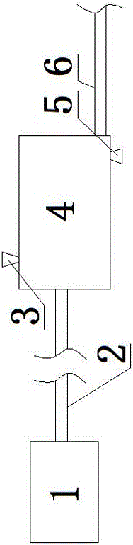
[0095] The new structural column concrete pumping system includes a pneumatic power device 1, the front end of a concrete storage container 4 connected to the pneumatic power device 1 through a power delivery pipe 2, and a concrete delivery pump pipe 6 is arranged under the rear end of the concrete storage container 4 The top of the concrete holding container 4 is provided with a flange cover-sealed feed port 3; the bottom is provided with a flange cover-sealed cleaning port 5; the feed port 3 is provided with a pressure relief device equipped with a ball valve;

[0096] Both the power delivery pipe 2 and the concrete delivery pump pipe 6 are welded with the concrete holding container 4 using seamless steel pipes; the pneumatic power device 1 includes an air compressor;

[0097] The specific construction method of the described structural column concrete pumping system is:...


PUM

PropertyMeasurementUnit
Slumpaaaaaaaaaa

Abstract

The invention discloses a novel constructional column concrete pumping system which comprises a pneumatic power device. The pneumatic power device is connected with the front end of a concrete container through a power delivery pipe, and a concrete delivery pump pipe is arranged on the lower portion of the back end of the concrete container; the top of the concrete container is provided with a feeding port sealed by a flange cover, the lower portion of the concrete container is provided with a cleaning port sealed by a flange cover, and a pressure discharge device which is additionally provided with a ball valve is arranged beside the feeding port. By means of the novel constructional column concrete pumping system, pouring can be completed at a time, chiseling and column head repairing are not needed, therefore, the quality is effectively guaranteed, and work and labor are saved; when two persons operate a pumping machine, 80 constructional columns can be poured in a day, and when a traditional method is adopted, only 20 constructional columns can be poured by two persons in a day; the cost for producing the pumping machine through experimental machining in a matched mode is only 5,000 yuan. Pipeline lengthening and pumping air pressure mechanomotive force designing can be conduced on the pumping machine according to a specific construction calculation method, therefore, the construction efficiency of a construction enterprise is greatly improved, the construction quality is improved, and enterprise competitiveness is enhanced.

Description

technical field [0001] The invention relates to the field of construction, in particular to a concrete pumping system and a calculation method thereof during the pouring of structural columns. Background technique [0002] In building construction, after the completion of the secondary structure masonry, the concrete of the structural column must be poured; however, the traditional method of pouring the concrete of the structural column is to manually transfer the concrete to the top of the structural column, and then carry out the pouring of the concrete through the reserved material inlet. When the material is poured to about 20cm from the top of the column, the column cap should be repaired again, and the protruding part should be chiseled after the column cap is repaired. This construction method is very troublesome, can not guarantee the construction quality of the structural column concrete, and wastes manpower and material resources. [0003] At present, traditional ...

Claims


Application Information

Patent Timeline
IPC IPC(8): E04G21/02
CPCE04G21/02
Inventor 王磊吴文兵
Owner CHINA CONSTR SEVENTH ENG DIVISION CORP LTD
Why Eureka
Try Eureka