


Quick Research
Generate reliable direction feasibility study reports for your R&D in just a few steps.

Technical Q&A
Discover and master advanced knowledge NOW. Basics, ideas, possibilities, all at once.

Find Solutions
As an expert in R&D theories, this can generate solutions to your technical problems instantly.

Evaluate Feasibility
Analyze your overall solution with one click, know your potential R&D risks in advance.

Monitor Landscape
Get weekly tech updates, stay abreast of the latest tech innovations and key insights.
Dust collecting and treating device
A dust collection and processing device technology, applied in the field of dust collection and processing devices, dust collection and processing devices at the outer outlet of the vibrating screen, can solve the problems of inconvenient collection, dust flying, etc., achieve simple and convenient disassembly and maintenance, save operating costs, The effect of a clean and tidy working environment
- Summary
- Abstract
- Description
- Claims
- Application Information
AI Technical Summary
Problems solved by technology
Method used
Image

Examples
Embodiment 1
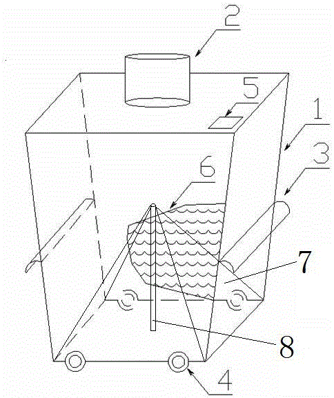
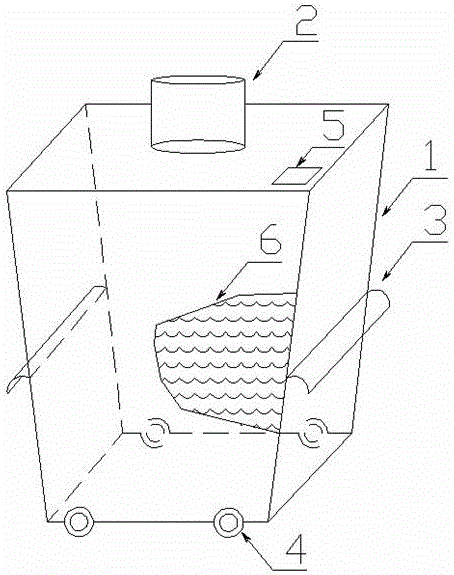
[0025] The collection box is in the shape of a square column, and the whole box is in a state of natural shrinkage with a large top and a small bottom, so that a slope is formed between all side inner walls and the bottom of the box, which is conducive to the natural fall of dust. The joints between the inner walls are equipped with concave circular arc powder guide strips. This concave circular arc powder guide strips are used to place the dust embedded in the joint between the inner walls and the follow-up treatment of the dust. To be clean and efficient.
[0026] Since a dust collection balance device is provided in the box, the device is formed by connecting a collection cover and a support rod. The support rod is arranged at the bottom center of the collection box, and the collection cover is arranged on the support rod to collect The top of the cover is connected to the top of the support rod, and the bottom of the collection cover is connected to the bottom side of the ...
Embodiment 2
[0028] The dust collection and treatment device includes a collection box body, a water level setting line is arranged in the collection box body, a dust collection port is arranged on the top of the collection box body, a dust collection balance device is arranged in the collection box body; There are rollers, and the inner wall of the collection box is provided with a powder guide groove.
[0029] At the same time, an observation hole is provided on the top of the collection box. The collection box is in the shape of a column. The top area of the collection box is larger than the bottom area of the collection box. There is an 80-degree gap between the inner wall of the collection box and the bottom of the collection box. Included angle, the connecting seam between the inner wall and the inner wall is provided with a powder guiding strip; the powder guiding strip is a concave circular arc flow guiding strip.
[0030] Further, the side of the collection box is provided wit...
PUM
 Abstract
Description
Claims
Application Information
 - R&D Engineer
- R&D Manager
- IP Professional
- Industry Leading Data Capabilities
- Powerful AI technology
- Patent DNA Extraction
Browse by: Latest US Patents, China's latest patents, Technical Efficacy Thesaurus, Application Domain, Technology Topic, Popular Technical Reports.
© 2024 PatSnap. All rights reserved.Legal|Privacy policy|Modern Slavery Act Transparency Statement|Sitemap|About US| Contact US: help@patsnap.com