
Avalanche photodiode detection array applicable to ultra high-speed quantum secure communication system

A quantum secure communication and avalanche photoelectric technology, applied in the field of detection arrays, can solve the problems of APD not meeting the demand, the coding rate of the communication system not improving, limiting the coding rate of quantum secure communication, etc.

Inactive Publication Date: 2016-11-16
UNIV OF SHANGHAI FOR SCI & TECH
View PDF3 Cites 7 Cited by
  • Summary
  • Abstract
  • Description
  • Claims
  • Application Information

AI Technical Summary

Problems solved by technology

[0003] However, InGaAs / InPAPD single-photon detectors are usually designed to achieve 2.5Gbps traditional optical fiber communication. Considering the frequency response characteristics of APD and the limitation of the signal-to-noise ratio of the final detector, the maximum repetition frequency of such single-photon detectors is about 2.5GHz, which greatly limits the further improvement of the coding rate of quantum secure communication
With the further improvement of the quantum security communication rate, the current APD has gradually failed to meet the demand
In addition, the photon number resolution performance of a single APD detector is far from meeting the requirements of the application
Based on multiplexing schemes such as time division multiplexing, the system operating rate can be increased through the APD array, and then the uncertainty in the single-photon beam splitting process will lead to a decrease in the detection efficiency of the system, so that the coding rate of the communication system has not improved.

Method used


Image

  • Avalanche photodiode detection array applicable to ultra high-speed quantum secure communication system
  • Avalanche photodiode detection array applicable to ultra high-speed quantum secure communication system

Examples


Embodiment 1

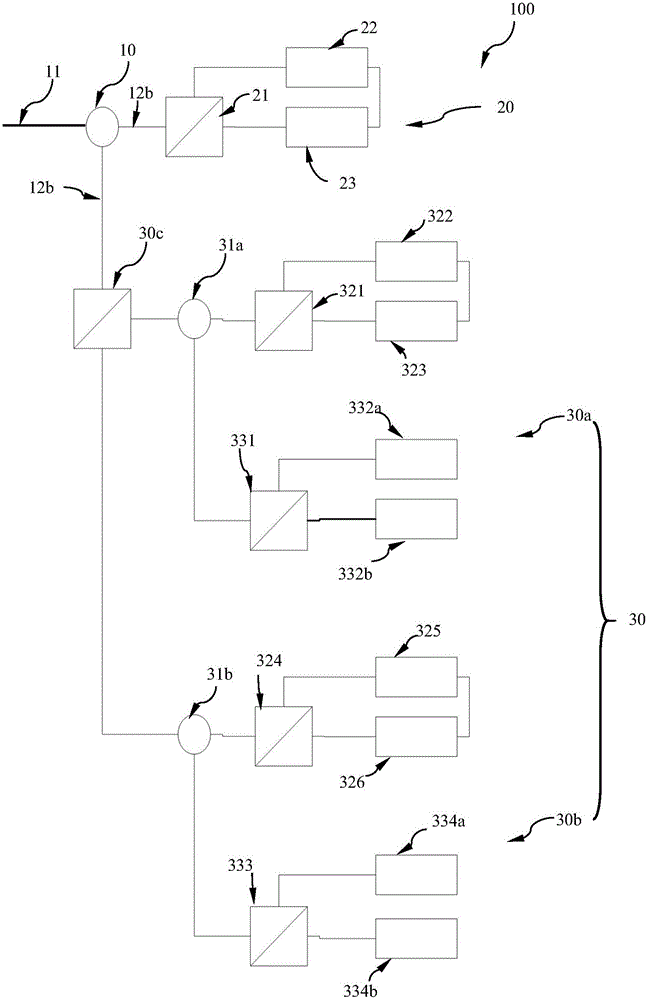
[0018] figure 1 It is a schematic structural diagram of an avalanche photodiode detection array suitable for an ultra-high-speed quantum secure communication system in this embodiment.

[0019] Such as figure 1 As shown, an avalanche photodiode detection array 100 suitable for an ultra-high-speed quantum secure communication system has a first circulator 10 , a first Sagnac interference (Sagnac) ring 20 and a spectroscopic detection unit 30 . in,

[0020] The first circulator 10 has an input optical path 11 and two output optical paths 12a, 12b, and the input optical path 11 and the external signal light are welded together at 45°.

[0021] The first Sagnac interference (Sagnac) ring 20 is composed of a first polarization beam splitter 21 , a first phase modulator 22 and a first Faraday rotator 23 connected clockwise through an optical path (such as an optical fiber).

[0022] The first polarization beam splitter 21 has three optical paths, the common end is connected to an...


PUM


Abstract

The invention discloses an avalanche photodiode detection array applicable to an ultra high-speed quantum secure communication system. The detection array is used for receiving external signal light and detecting information. The detection array comprises a first circulator which is equipped with an input light path and two output light paths, and is used for receiving the external input signal light, outputting the signal light in two ways and controlling the output direction of the signal light; a first Sagnac interference ring; and two spectroscopic detection units. Each spectroscopic detection unit comprises a Sagnac interference ring and a single photon detection assembly. Each Sagnac interference ring is composed of a polarization beam splitter, a phase modulator and a Faraday rotator which are connected through a light path clockwise. Each polarization beam splitter is connected with one output light path of the circular. Each single photon detection assembly is composed of a detection polarization beam splitter, and two single photon detectors connected with the detection polarization beam splitter through the light path. The total detection efficiency of the single photon detection array is avoided from being reduced, the working speed of the quantum secure communication system is improved, and moreover, the code rate is improved.

Description

technical field [0001] The invention relates to a detection array of a quantum security communication system, which belongs to the field of optical communication. Background technique [0002] Single-photon detection technology is currently a research hotspot in the world, and it has shown a mutually reinforcing development trend with quantum optics. In terms of new principles of single-photon detection, especially the single-photon detection technology in the 1550nm band has developed rapidly, and new detection methods such as superconducting detectors have emerged. For example, both superconducting state transition detectors and superconducting strip detectors are based on the superconducting pyroelectric effect. The former has a high photon number resolution capability, and its maximum resolvable photon number exceeds 11, but the count rate is only 20kHz; the latter The detection rate reaches 1GHz, but due to coupling and other problems, its detection efficiency is very ...

Claims


Application Information

Patent Timeline
Patent Type & Authority Applications(China)
IPC IPC(8): H04L9/08
CPCH04L9/0852
Inventor 梁焰曾和平
Owner UNIV OF SHANGHAI FOR SCI & TECH
Learn More