
Magnetic levitation switch reluctance flywheel motor and decoupling control method

A technology of flywheel motor and switched reluctance, which is applied in the direction of electrical components, magnetic attraction or thrust holding device, etc., can solve the problems of unfavorable magnetic levitation motor high-speed adaptability, affecting the mechanical strength of the system, and easy to increase the axial length, etc., to achieve Improve radial suspension performance, solve difficult tracking and chopping control, and improve the effect of radial load capacity

Active Publication Date: 2016-11-16
NANJING INST OF TECH
View PDF6 Cites 1 Cited by
  • Summary
  • Abstract
  • Description
  • Claims
  • Application Information

AI Technical Summary

Problems solved by technology

However, when the composite rotor is running with load, it is easy to increase the axial length and the volume of the whole machine, which affects the mechanical strength of the system and limits the increase of the critical speed, which is not conducive to the high-speed adaptability of the magnetic levitation motor.

Method used


Image

  • Magnetic levitation switch reluctance flywheel motor and decoupling control method
  • Magnetic levitation switch reluctance flywheel motor and decoupling control method
  • Magnetic levitation switch reluctance flywheel motor and decoupling control method

Examples


Embodiment Construction

[0022] In order to enable those skilled in the art to better understand the technical solutions of the present invention, the present invention will be further described in detail below in conjunction with the accompanying drawings and specific embodiments. Hereinafter, embodiments of the present invention will be described in detail, examples of which are shown in the accompanying drawings, wherein the same or similar reference numerals denote the same or similar elements or elements having the same or similar functions throughout. The embodiments described below by referring to the figures are exemplary only for explaining the present invention and should not be construed as limiting the present invention.

[0023] Those skilled in the art can understand that, unless otherwise defined, all terms (including technical terms and scientific terms) used herein have the same meaning as commonly understood by one of ordinary skill in the art to which this invention belongs. It shou...


PUM


Abstract

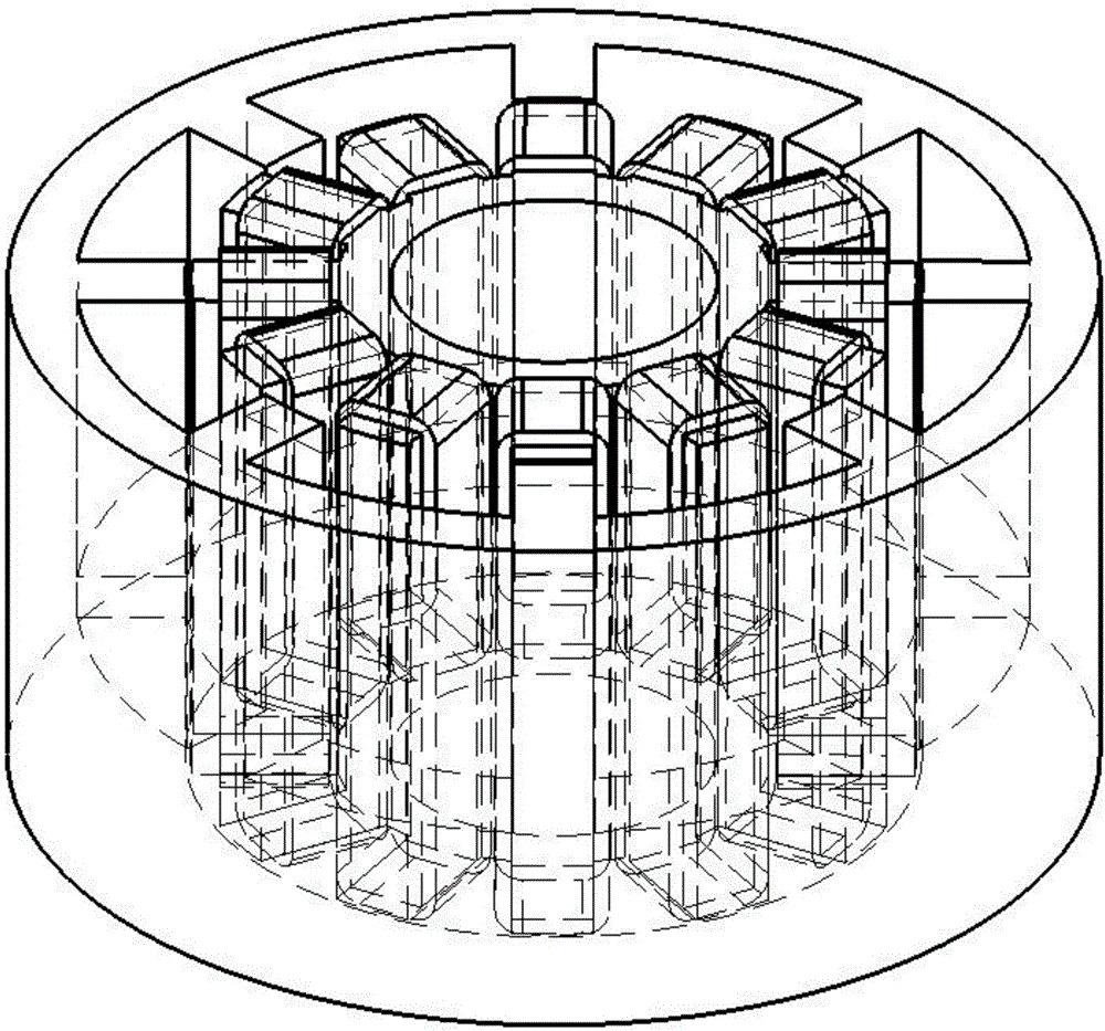
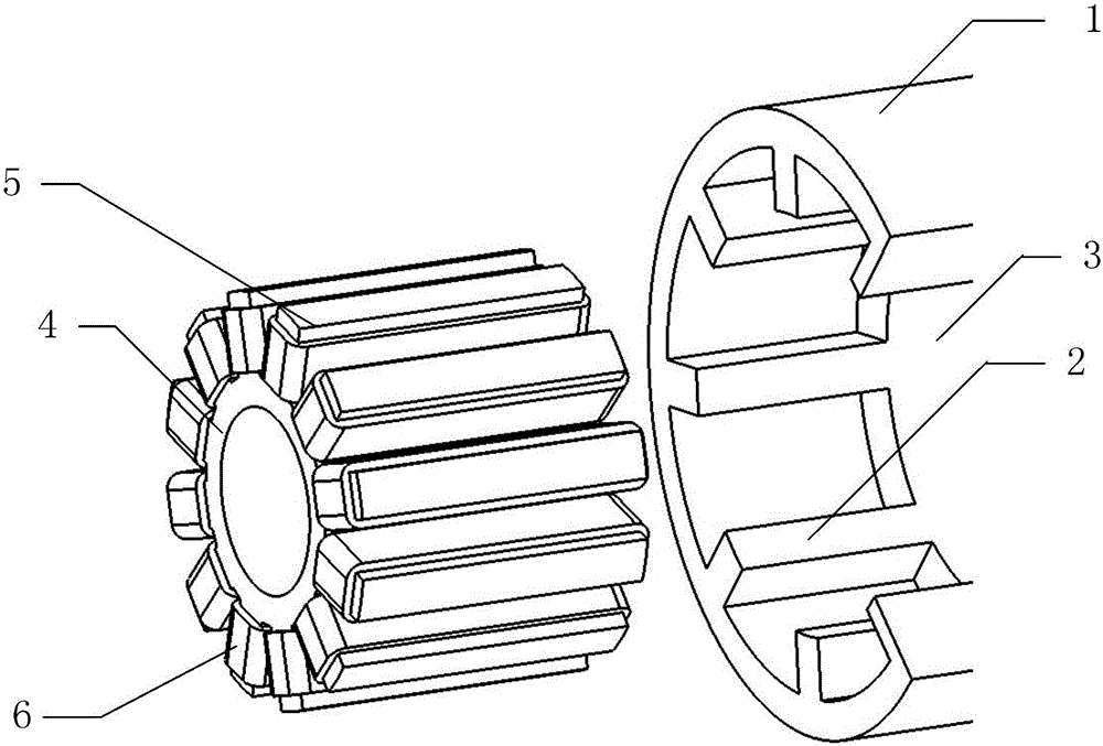
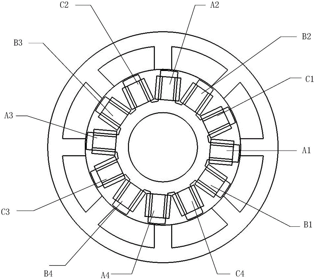
Embodiments of the invention disclose a magnetic levitation switch reluctance flywheel motor and a decoupling control method. The magnetic levitation switch reluctance flywheel motor comprises an outer rotor iron core (1) and a stator iron core (4), wherein the outer rotor iron core (1) and the stator iron core (4) are nested in sequence in a concentric manner; the outer rotor iron core (1) comprises a salient pole rotor (2) and a cylindrical rotor (3) in an axial recombination manner; eight rotor salient poles are arranged on the inner wall of the salient pole rotor (2) at equal intervals; each rotor salient pole has no winding; twelve stator salient poles (5) are arranged on the outer wall of the stator iron core (4) at equal intervals; and each stator salient pole is wound by a set of stator windings (6). By adoption of the embodiments of the magnetic levitation switch reluctance flywheel motor and the decoupling control method, the decoupling control on an electric / power generation function and a radial levitation function can be realized; the flywheel rotor strength can be enhanced; the size of the overall machine can be reduced; the dynamic characteristics and the stability of the system are improved; and the high-adaptivity characteristic of the magnetic levitation switch reluctance flywheel motor is further performed.

Description

technical field [0001] The invention relates to the technical field of magnetic levitation motors, in particular to a magnetic levitation switched reluctance flywheel motor and a decoupling control method. Background technique [0002] The magnetic levitation switched reluctance motor generates a controllable levitation force acting on the rotor by changing the original magnetic field distribution of the switched reluctance motor, thereby suspending the rotor in space. On the basis of retaining the performance advantages of the switched reluctance motor, Further eliminates the friction loss caused by mechanical bearings, and does not require lubrication devices. It can be operated by electric or power generation at high-speed and ultra-high speed, and has broad application prospects in many fields such as industry, chemical industry, biology and military industry. Using the magnetic levitation switched reluctance motor as the flywheel motor can effectively reduce the volume...

Claims


Application Information

Patent Timeline
Patent Type & Authority Applications(China)
IPC IPC(8): H02N15/00
CPCH02N15/00
Inventor 周云红孙玉坤张亮
Owner NANJING INST OF TECH
Learn More