
Adjustable power equalizer with combined link

An equalizer, link technology

Active Publication Date: 2016-11-16
CHINA ELECTRONIS TECH INSTR CO LTD
View PDF9 Cites 4 Cited by
  • Summary
  • Abstract
  • Description
  • Claims
  • Application Information

AI Technical Summary

Problems solved by technology

Due to problems such as material consistency, there is often a certain deviation between the measured results of the equalizer and the simulated results, and it is difficult to adjust the finished product. Therefore, it often takes multiple board tests to obtain the final required equalizer indicators, resulting in a lot of repetitive work and increasing design cost
[0003] Conventional power equalizers generally adopt one-time processing and forming, and the adjustable range is limited, such as figure 1 As shown, in general, it is only possible to fine-tune by connecting the branch extension line with a gold mesh. Due to consistency problems such as materials and assembly, there is often a large deviation between the equalizer simulation and the actual test results. Therefore, in order to obtain the ideal equalization effect, It is often necessary to repeatedly put into production several times according to the actual test to obtain the required equalizer. This experiment and debugging process has caused a lot of repeated work and increased the cost of the design.
Traditional finished equalizers are difficult to effectively adjust the equalization frequency, amplitude and phase, and the universal applicability is poor

Method used


Image

  • Adjustable power equalizer with combined link
  • Adjustable power equalizer with combined link
  • Adjustable power equalizer with combined link

Examples


Embodiment Construction

[0033] The following will clearly and completely describe the technical solutions in the embodiments of the present invention with reference to the accompanying drawings in the embodiments of the present invention. Obviously, the described embodiments are only some, not all, embodiments of the present invention. Based on the embodiments of the present invention, all other embodiments obtained by persons of ordinary skill in the art without making creative efforts belong to the protection scope of the present invention.

[0034] In the field of microwave and millimeter wave solid-state power amplifiers, the power flatness of power amplifier chips is difficult to achieve a high level, especially for broadband high-gain power amplifier circuits, the use of multi-cascaded high-gain amplifiers is likely to cause index deterioration and superposition, which affects the amplifier’s performance. Work stability and performance indicators have adverse effects. Therefore, power equalizati...


PUM


Abstract

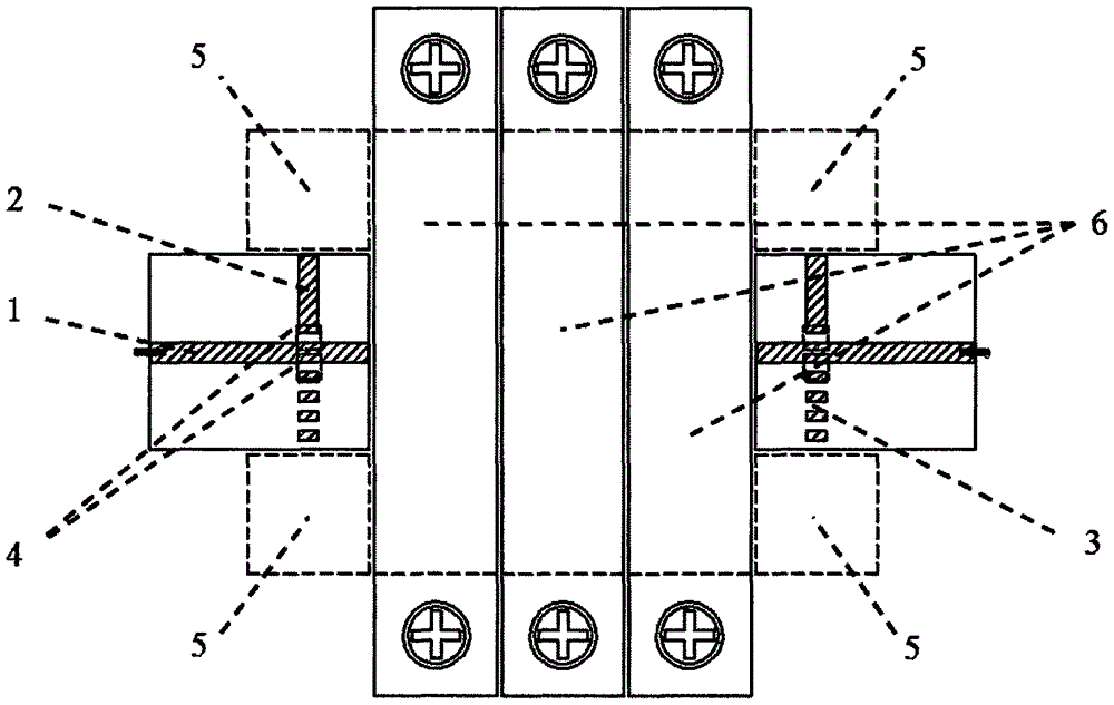
The invention proposes an adjustable power equalizer with a combined link. The adjustable power equalizer comprises a main circuit and adjustable part and a combined link part, wherein the main circuit and adjustable part comprises main circuit direct-connection modules and main circuit branch adjustment modules, each main circuit direct-connection module comprises a direct-connection line, a continuous strip line branch, spacing strip line branches and branch resistor positions, the continuous strip line branch is used for balancing a low-frequency point, the spacing strip line branches are used for balancing a high-frequency point, the main circuit branch adjustment modules are additionally arranged for compensation when the continuous strip line branch on the main circuit direct-connection module cannot meet frequency point balancing requirement, the combined link part comprises one or more unit module positions, the unit module positions are used for assembling a selectable branch module and / or a phase adjustment module, and the width of the selectable branch module or the phase adjustment module is an integer multiple of the width of the unit module positions. Compared with a traditional power equalizer, the novel equalizer structure proposed by the invention has the characteristics of high universal applicability, flexible and versatile link combinations and selections and simplicity in assembly and debugging.

Description

technical field [0001] The invention relates to the field of microwave and millimeter wave solid-state power amplifiers, in particular to an adjustable power equalizer with combined links. Background technique [0002] The development of microwave and millimeter-wave solid-state power amplifier technology has put forward higher requirements for power equalization technology. Not only does the equalizer need to achieve power equalization at more frequency points, it needs to have a larger power amplitude equalization range, but also requires the ability to balance power The signal transmission phase of the equalizer can be effectively adjusted, which brings greater challenges to the design of the equalizer. Due to problems such as material consistency, there is often a certain deviation between the measured results of the equalizer and the simulated results, and it is difficult to adjust the finished product. Therefore, it often takes multiple board tests to obtain the final ...

Claims


Application Information

Patent Timeline
Patent Type & Authority Applications(China)
IPC IPC(8): H01P5/04
CPCH01P5/04
Inventor 王琦宁曰民刘金现
Owner CHINA ELECTRONIS TECH INSTR CO LTD
Learn More