System and method for measuring static pulling force of claw-shaped hardware fitting at end part of high-voltage casing pipe of transformer

A high-voltage bushing and tensile force measurement technology, applied in the field of electric power, can solve the problem of difficulty in detecting the force of the claw-shaped fittings, and achieve the effect of improving the measurement accuracy

Active Publication Date: 2016-11-16
STATE GRID HENAN ELECTRIC POWER ELECTRIC POWER SCI RES INST +2
View PDF8 Cites 0 Cited by
  • Summary
  • Abstract
  • Description
  • Claims
  • Application Information

AI Technical Summary

Problems solved by technology

[0004] In view of this, the present invention provides a static tension measurement system and method for a horn-shaped fitting at the end of a transformer high-voltage bushing, which solves the problem that the actual force of the horn-shaped fitting at the end of a transformer bushing in an existing substation is difficult to detect, and can realize Convenient, real-time and accurate detection of the pull force of horn-shaped fittings, so as to monitor the use status of horn-shaped fittings and carry out timely maintenance or replacement

Method used


Image

  • System and method for measuring static pulling force of claw-shaped hardware fitting at end part of high-voltage casing pipe of transformer
  • System and method for measuring static pulling force of claw-shaped hardware fitting at end part of high-voltage casing pipe of transformer
  • System and method for measuring static pulling force of claw-shaped hardware fitting at end part of high-voltage casing pipe of transformer

Examples


Embodiment Construction

[0034] The preferred embodiments of the present invention will be described below in conjunction with the accompanying drawings. It should be understood that the preferred embodiments described here are only used to illustrate and explain the present invention, and are not intended to limit the present invention.

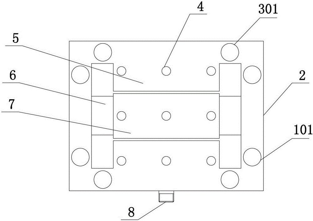
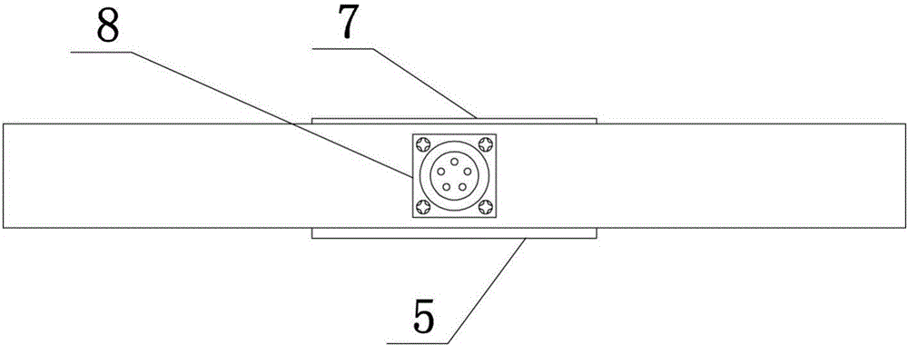
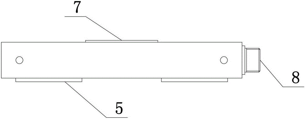
[0035] like figure 1 - Image 6 As shown, the present invention provides a static tension measurement system for transformer high-voltage bushing end horn-shaped fittings, comprising a frame 2, the frame 2 includes an upper beam, a lower beam, a left beam and a right beam, the upper beam of the frame 2 and the The lower beams are all provided with three holes 4 in the horizontal direction. A middle crossbeam is arranged in the middle of the frame, and the middle crossbeam includes a fixing part 7 and two connecting parts 6, and the two ends of the fixing part 7 are respectively arranged on the left and right crossbeams of the frame through the connecting parts 6. ...


PUM


Abstract

The invention disclose a system and method for measuring a static pulling force of a claw-shaped hardware fitting at an end part of a high-voltage casing pipe of a transformer. A frame body comprises an upper cross beam, a lower cross beam, a left cross beam, and a right cross beam. The upper and lower cross beams of the frame body are respectively provided with three holes in a horizontal direction. The central part of the frame body is provided with a central cross beam, and the central cross beam is provided with three holes in the horizontal direction. The holes on the upper, central and lower cross beams are corresponding in a vertical direction. The central cross beam comprises a fixed part and two connection parts, wherein two ends of the fixed part are disposed on the frame body through the two connection parts. The top of the fixed part is higher than the upper and lower cross beams in the horizontal direction, and the bottom of the fixed part is lower than the upper and lower cross beams in the horizontal direction. The upper, lower, left and right cross beams and the connection parts are respectively provided with a pulling force sensor. The system solves a problem that the stress of a claw-shaped hardware fitting at an end part of a casing pipe of a transformer of a conventional transformer substation is difficult to detect, and can achieve the convenient, real-time and precise detection of the pulling force of the claw-shaped hardware fitting.

Description

technical field [0001] The invention relates to the field of electric power, in particular to a static tension measuring system and method for a claw-shaped fitting at the end of a high-voltage bushing of a transformer. Background technique [0002] Fittings are iron or aluminum metal accessories widely used in power transmission lines. Most of the fittings need to withstand large tension during operation, and some of them must also ensure good electrical contact. Due to the unreasonable design of the wiring fittings at the end of the bushing of the UHV substation, the insufficient strength of the cover plate of the terminal at the end of the bushing, and the weak link in the sealing design, the lateral force of the terminal at the top of the bushing exceeds the design value, and the long-term effect Under the circumstances, the end of the bushing is deformed, the seal fails, and water enters, which eventually leads to an inter-turn short circuit fault in the main transforme...

Claims


Application Information

Patent Timeline
Patent Type & Authority Applications(China)
IPC IPC(8): G01L5/00G01L5/16G01L1/22
CPCG01L1/22G01L5/0033G01L5/16G01L5/161
Inventor 吕中宾钱诗林寇晓适谢凯任鹏亮张嵩阳张远王广周陈豪然王飞郭星李媛吴豫蔡永平
Owner STATE GRID HENAN ELECTRIC POWER ELECTRIC POWER SCI RES INST
Why Eureka
Try Eureka