Novel mechanical transmission structure and device with mechanical transmission structure

A new type of mechanical transmission technology, applied in transmission devices, friction transmission devices, electromechanical devices, etc., can solve the problems of increasing elastic deformation of synchronous belts, affecting transmission efficiency and accuracy, and increasing power transmission delays, so as to improve transmission accuracy. and speed, easy installation and commissioning, fast power delivery

Inactive Publication Date: 2016-11-16
杨晨晨
View PDF6 Cites 0 Cited by
  • Summary
  • Abstract
  • Description
  • Claims
  • Application Information

AI Technical Summary

Problems solved by technology

[0004] Fused deposition type (FDM) 3D printers and other high-speed and low-load machines mostly use narrow synchronous belts with various transmission structures. However, as the size of the machine increases and the transmission distance increases, the length of the synchronous belt increases accordingly. The amount of elastic deformation increases, and because the force changes direction many times during the power transmission process, the delay in power transmission increases, which affects the transmission efficiency and accuracy, and restricts the further development of large-scale machines, especially large-scale 3D printing machines.
[0005] In order to ensure working accuracy, large machines can only run at reduced speed, not at full speed

Method used


Image

  • Novel mechanical transmission structure and device with mechanical transmission structure
  • Novel mechanical transmission structure and device with mechanical transmission structure
  • Novel mechanical transmission structure and device with mechanical transmission structure

Examples


Embodiment 1

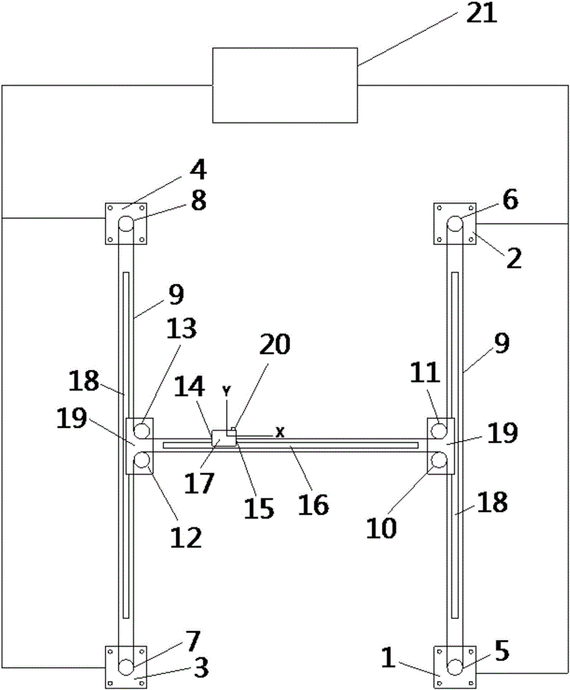
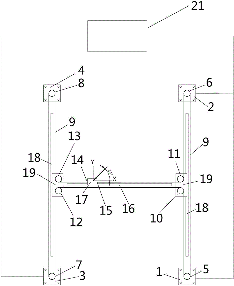
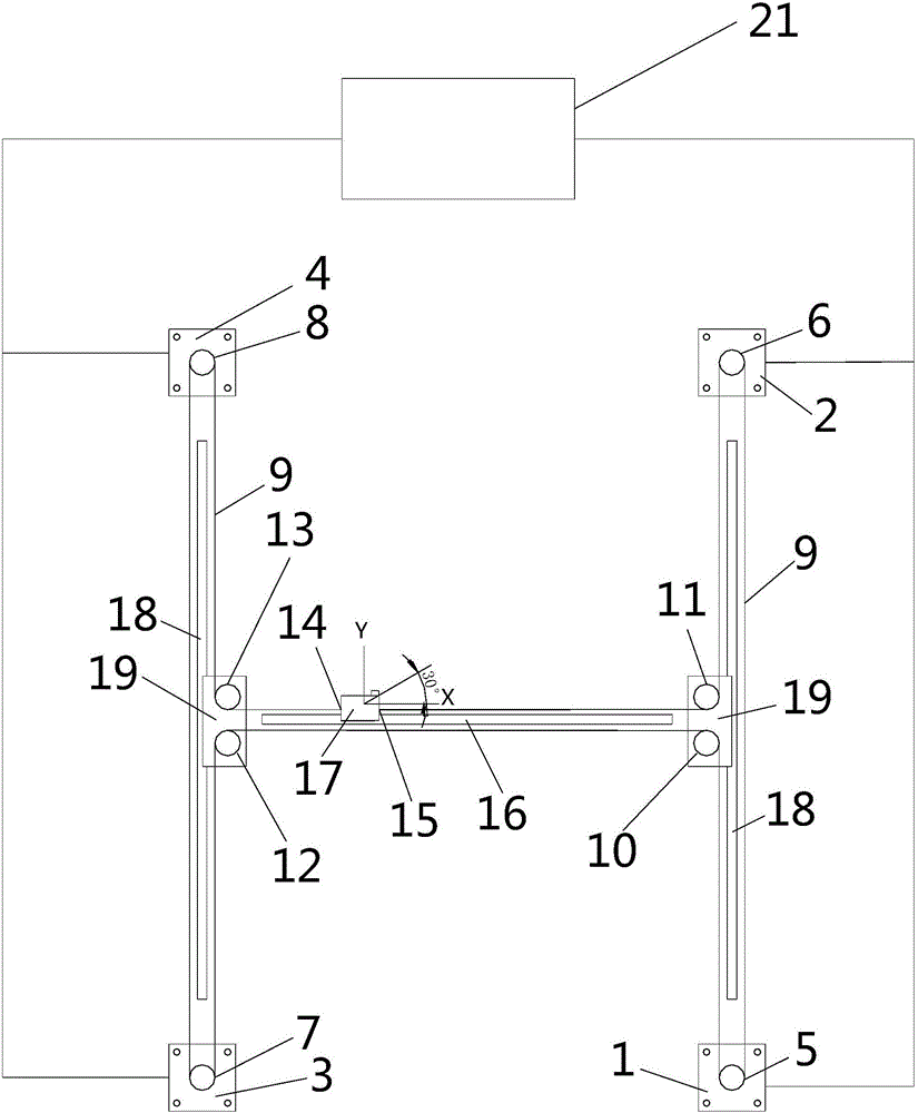
[0043] Embodiment 1: A kind of novel mechanical transmission structure, its structure is as figure 1 shown, including:

[0044] The Y-direction slide rails 18 located on the left and right sides have a Y-direction slide block 19 on each Y-direction slide rail 18; two Y-direction slide blocks 19 are fixedly connected to the two ends of the same X-direction slide rail 16, An X-direction slide block 17 is provided on the X-direction slide rail 16 , and the X-direction slide rail 16 is perpendicular to the Y-direction slide rail 18 .

[0045] The upper and lower ends of the left Y direction slide rail 18 are respectively provided with a fourth motor 4 and the third motor 3; the upper and lower ends of the right Y direction slide rail 18 are respectively provided with a second motor 2 and a second motor 2 A motor 1 .

[0046] Wherein, the first synchronous wheel 5 is installed on the first motor 1, the second synchronous wheel 6 is installed on the second motor 2, the 3rd synchro...

Embodiment 2

[0061] Embodiment 2: A device, on which a two-axis linkage mechanical structure of the X-axis and the Y-axis is installed. Wherein, the structure is the structure shown in Embodiment 1.

Embodiment 3

[0062] Embodiment 3: a 3D printer, the 3D printer has at least a two-axis and two-linkage structure. Wherein, the printer adopts the transmission structure shown in Embodiment 1, and the working module 20 on the printer is replaced by an extrusion head.


PUM


Abstract

The invention relates to a novel mechanical transmission structure and a device with the mechanical transmission structure. The mechanical transmission structure mainly comprises Y-direction slide rails on the left and right sides, an X-direction slide rail, and four motors, wherein a Y-direction sliding block is arranged on each Y-direction slide rail; the X-direction slide rail is fixedly connected with the Y-direction sliding blocks; an X-direction sliding block is arranged on the X-direction slide rail; the motors are positioned on the outer sides of the end parts of the Y-direction slide rails; a driving wheel is mounted on a main shaft of each motor; two driven wheels are arranged on each of the two Y-direction sliding blocks; and a synchronous belt is fixedly connected with the X-direction sliding block after being wound around the four driving wheels and the four driven wheels. The transmission structure provided by the invention can perform two-shaft linkage, and has the advantages of high transmission accuracy and reliable service life.

Description

technical field [0001] The present invention relates to the related technical field of mechanical transmission, and in particular relates to a novel mechanical transmission structure and a device with the mechanical transmission structure. Background technique [0002] 3D printer is a device of rapid prototyping technology, and Fused Deposition Modeling (FDM) is one of the mainstream technologies of 3D printing. It utilizes the hot-melt type and adhesiveness of thermoplastic materials (ABS or PLA, peek, etc.), and heats the thermoplastic materials into a molten state in the printing nozzle. Under the control of the set program, the printing nozzle moves along the X-Y plane along the contour trajectory of the model. After being extruded, the printing material solidifies rapidly and bonds with the surrounding materials. Each layer is accumulated on the previous layer. Until the accumulation of layers according to the model is completed. [0003] Because the synchronous belt ...

Claims


Application Information

Patent Timeline
Patent Type & Authority Applications(China)
IPC IPC(8): F16H19/06H02K7/10
CPCF16H19/06F16H2019/069H02K7/1004
Inventor 杨晨晨
Owner 杨晨晨
Why Eureka
Try Eureka