
Adjustable damping feedback energy suspension system with driving behavior prediction model and control method of adjustable damping feedback energy suspension system

A predictive model and suspension system technology, applied in the field of energy-feeding suspension, can solve the problems of low energy conversion efficiency and no adjustment damping coefficient, etc., and achieve the effects of improving handling stability, simple structure, and simple mechanical structure

Active Publication Date: 2016-11-16
JIANGSU UNIV
View PDF7 Cites 10 Cited by
  • Summary
  • Abstract
  • Description
  • Claims
  • Application Information

AI Technical Summary

Problems solved by technology

The piezoelectric power generation type damping adjustable oil-air suspension disclosed in the patent number 201310171296.9 uses piezoelectric materials for energy recovery, and the energy conversion efficiency is not high
And no specific algorithm for adjusting the damping coefficient is given, ignoring the requirements of different driving behaviors on the suspension damping coefficient

Method used


Image

  • Adjustable damping feedback energy suspension system with driving behavior prediction model and control method of adjustable damping feedback energy suspension system
  • Adjustable damping feedback energy suspension system with driving behavior prediction model and control method of adjustable damping feedback energy suspension system

Examples


example 1

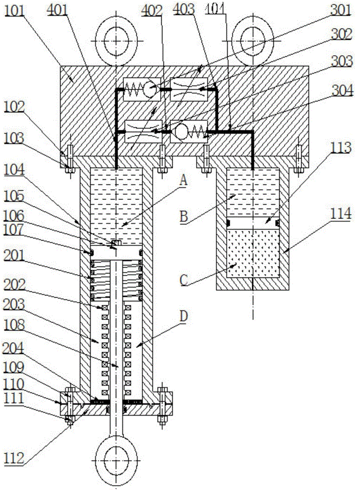
[0057] Example 1: When the vehicle installed with this system is running straight at a constant speed, the electronic control unit will continuously adjust the flow rate of the speed control valve according to the road conditions to achieve the effect of adjusting the damping force and ensure the best shock absorption effect of the vehicle. When the oil-gas spring works in the compression stroke, the piston 106 moves upward, the volume of chamber A decreases, the hydraulic oil enters chamber B through the second check valve 303 and the second speed regulating valve 304, the floating piston 113 of chamber B moves downward, and the nitrogen gas The volume of the piston is compressed, and the spring stiffness increases; when the piston spring works in the stretching stroke, the piston moves downward, the space in the A chamber increases to form a vacuum, the hydraulic oil in the B chamber enters the A chamber, and at the same time, the floating piston moves upward, and the nitrogen...


PUM


Abstract

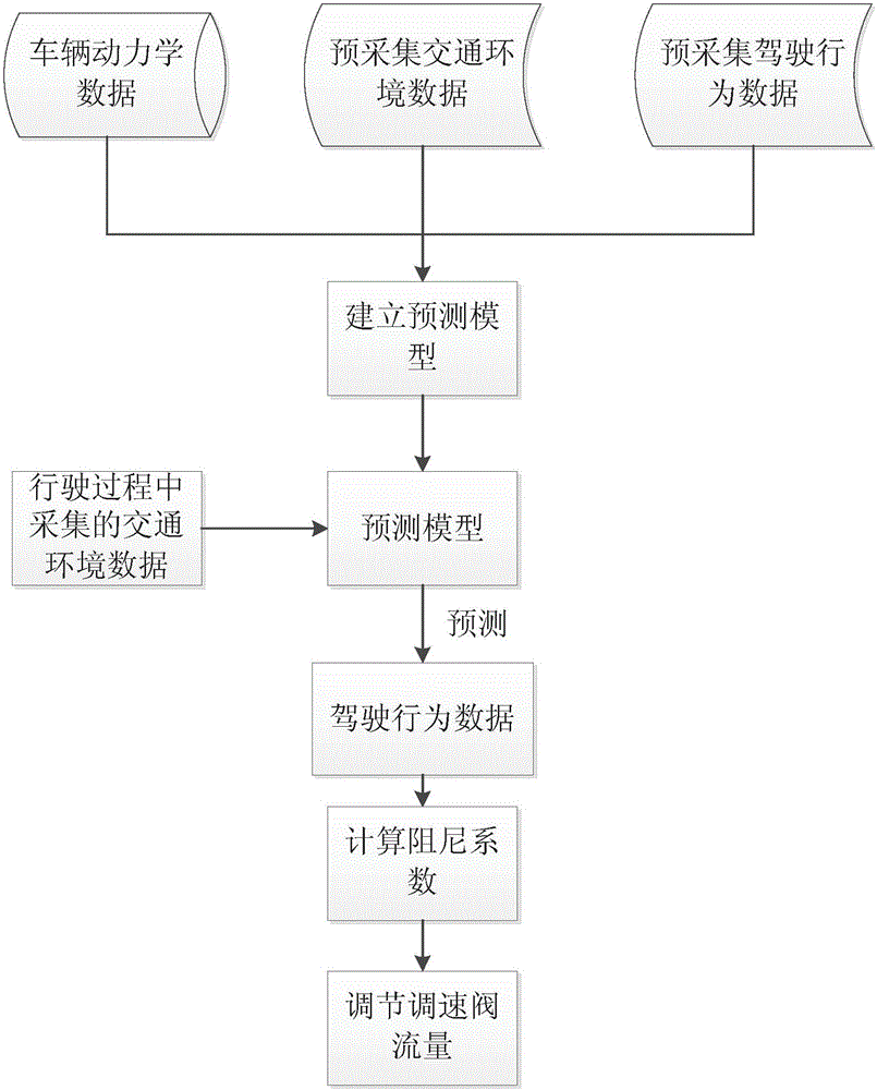
The invention relates to an adjustable damping feedback energy suspension system with a driving behavior prediction model and a control method of the adjustable damping feedback energy suspension system. A hydro-pneumatic spring comprises a hydro-pneumatic spring main body, a feedback energy mechanism and a damping force control mechanism. An electronic control unit is connected with the damping force control mechanism, a traffic environment data acquisition module and a driving behavior data acquisition module. The traffic environment data acquisition module is used for judging whether other vehicles exist around a self vehicle or not and collecting the distance between the self vehicle and the front vehicle, the distance between the self vehicle and the rear vehicle, speed information of the front vehicle and speed information of the rear vehicle. The driving behavior data acquisition module is used for acquiring the horizontal rotating angle of the head of a driver in the driving process, the treading stroke and the frequency of an accelerator pedal and the treading stroke and the frequency of a brake pedal. The damping force control mechanism is used for adjusting the damping coefficient of the hydro-pneumatic spring. The feedback energy mechanism is used for recycling vibration energy of the vehicle in the running process. Meanwhile, according to the driving behavior prediction model, a suspension can predict the driving behavior in advance and adjust performance parameters in time according to the traffic environment so that the driving smoothness and the operating stability can be improved.

Description

technical field [0001] The invention relates to a vehicle, in particular to an energy-feeding suspension and a control method that can predict upcoming driving behaviors and automatically adjust performance parameters according to the traffic environment. Background technique [0002] Suspension, as the connecting part of the force transmission between the car frame and the axle, its function is to transmit the force and moment between the wheel and the frame, and buffer the impact caused by the uneven road surface, so as to improve the ride comfort and operation stability of the vehicle sex. [0003] Because the parameters of the passive suspension cannot be adjusted, it can only ensure that the vehicle has good shock absorption performance under certain working conditions. Although the parameters of active suspension can be adjusted, it has not been effectively promoted because of its large energy consumption. [0004] Aiming at the problems of passive suspension and act...

Claims


Application Information

Patent Timeline
Patent Type & Authority Applications(China)
IPC IPC(8): B60G11/30B60G17/015
CPCB60G11/30B60G17/015B60G2202/154
Inventor 汪若尘谢辰阳孟祥鹏陈龙
Owner JIANGSU UNIV
Learn More