
Machining device and method for conical thin wall shell body

A technology of thin-walled shells and processing devices, applied in metal processing equipment, manufacturing tools, turning equipment, etc., can solve problems such as low efficiency, large clamping and alignment errors, large clamping deformation, difficult parts dimensional accuracy indicators, etc., to achieve Easy to meet the dimensional accuracy requirements of parts, high processing dimensional accuracy, and the effect of meeting the dimensional accuracy requirements of parts

Active Publication Date: 2016-11-16
HUBEI SANJIANG AEROSPACE WANFENG TECH DEV
View PDF7 Cites 21 Cited by
  • Summary
  • Abstract
  • Description
  • Claims
  • Application Information

AI Technical Summary

Problems solved by technology

[0017] The invention provides a machining device and a machining method for a conical thin-walled shell, which solves the problem of the low efficiency of the common machining method for thin-walled parts of this special structure, large errors in clamping and alignment, and large clamping Deformation, it is difficult to meet the dimensional accuracy index of the part

Method used


Image

  • Machining device and method for conical thin wall shell body
  • Machining device and method for conical thin wall shell body
  • Machining device and method for conical thin wall shell body

Examples


Embodiment Construction

[0046] In order to make the object, technical solution and advantages of the present invention clearer, the present invention will be further described in detail below in conjunction with the accompanying drawings and embodiments. It should be understood that the specific embodiments described here are only used to explain the present invention, not to limit the present invention. In addition, the technical features involved in the various embodiments of the present invention described below can be combined with each other as long as they do not constitute a conflict with each other.

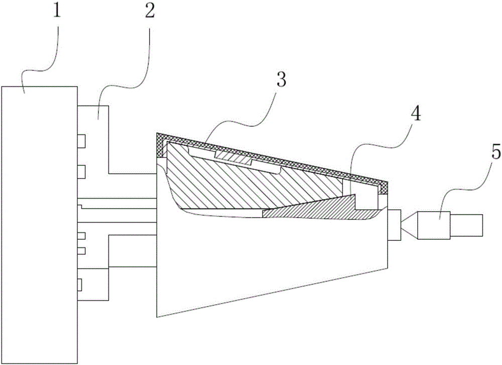
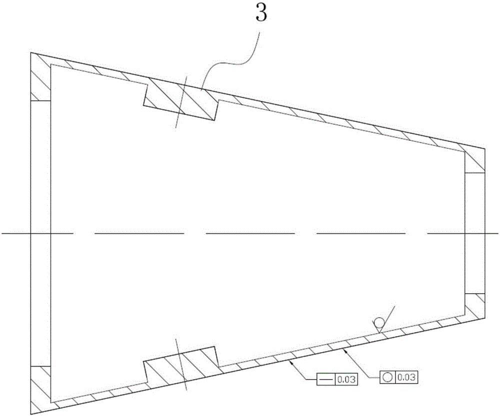
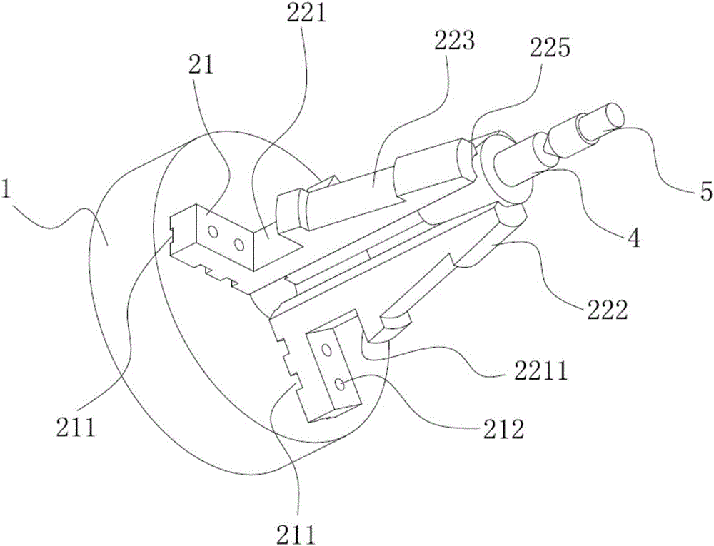
[0047] Figure 1 ~ Figure 4 It is a schematic diagram of a preferred embodiment of the present invention. The processing device of the present embodiment comprises: a chuck 1, a raised mounting block 11 is provided on the chuck 1, and a threaded hole (not shown) is provided on the mounting block 11; three soft jaws 2 are equilateral triangles Distributed and installed on the chuck 1, the soft ...


PUM


Abstract

The invention discloses a machining device and method for a conical thin wall shell body. The machining device comprises a chuck, three soft claws and a positioning tail cone, wherein the three soft claws are distributed in an equilateral triangle mode and installed on the chuck; and the front end shape of the positioning tail cone is matched with the shape of a conical groove, and the rear end of the positioning tail cone is provided with a centre hole. According to the machining device and method for the conical thin wall shell body, a clamping method that the soft claws with elastic claw parts are matched with the positioning tail cone, the positioning tail cone supports the tails of the soft claws, a center abuts against the positioning tail cone and enables the positioning tail cone to unfold the soft claws so that the soft claws can support the inner wall of a component is adopted, and the inner wall of the component and the inner side surface of the large end of the component are positioned. The soft claws support the inner wall, a lathe automatic centering effect and positioning of the positioning tail cone are combined, and the effect that the gyration center of the component and a lath spindle are concentric after clamping is ensured, so that quick clamping in the component machining process can be achieved, the gyration center of the component is automatically centered, and precise positioning is conducted; and the efficiency is high, clamping deformation is small, the machining dimensional precision of the component is high, the wall thickness is uniform, and the component dimensional precision requirements can be met more easily.

Description

technical field [0001] The invention belongs to the field of machining of thin-walled parts, and in particular relates to a machining device and a machining method of a thin-walled conical shell. Background technique [0002] In recent years, in the machining production process of Dazhong Machinery Factory, the processing proportion of thin-walled parts is increasing, and the shape is becoming more and more complex, and the requirements for dimensional accuracy and surface roughness are getting higher and higher. Especially with the rapid development of manufacturing technology, the casting process, as a less and no cutting process, has been widely used in the fields of machinery, metallurgy, aerospace and other fields, and can cast various high-strength precision thin-walled castings with complex shapes. For example, cast thin-walled shells have gradually replaced welded, riveted or forged shells, which can not only greatly reduce costs and shorten the manufacturing cycle, ...

Claims


Application Information

Patent Timeline
IPC IPC(8): B23B31/10B23B31/40B23B5/00
CPCB23B5/00B23B31/10B23B31/404
Inventor 王元成杨蒲莉罗志鹏孙旭杨普文刘杰朱幼芬
Owner HUBEI SANJIANG AEROSPACE WANFENG TECH DEV
Learn More