
Device and method for measuring pulse wave velocity in small range based on light reflection method

A pulse wave, small-scale technology, used in diagnostic recording/measurement, medical science, sensors, etc., can solve problems such as large time delay, troublesome operation, and error

Active Publication Date: 2016-11-16
CHENGDU UNIVERSITY OF TECHNOLOGY
View PDF4 Cites 4 Cited by
  • Summary
  • Abstract
  • Description
  • Claims
  • Application Information

AI Technical Summary

Problems solved by technology

[0003] In 2013, Yang Gang and others developed a measurement device and method for pulse wave velocity physiological parameters based on photovolume, but the external circuit diagram is very complicated, and an analog filter is used for filtering, and the analog filter will produce a phase shift, so the measurement can be The time delay will have a large and unpredictable error
The operation is troublesome, and each person's physical condition is different. There is a lot of randomness in the estimation of the pulse peak, which is limited to the research stage

Method used


Image

  • Device and method for measuring pulse wave velocity in small range based on light reflection method
  • Device and method for measuring pulse wave velocity in small range based on light reflection method
  • Device and method for measuring pulse wave velocity in small range based on light reflection method

Examples


Embodiment 1

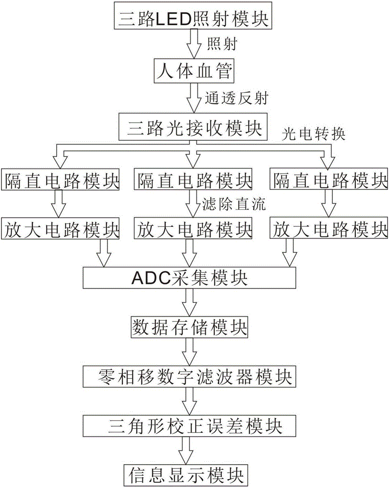
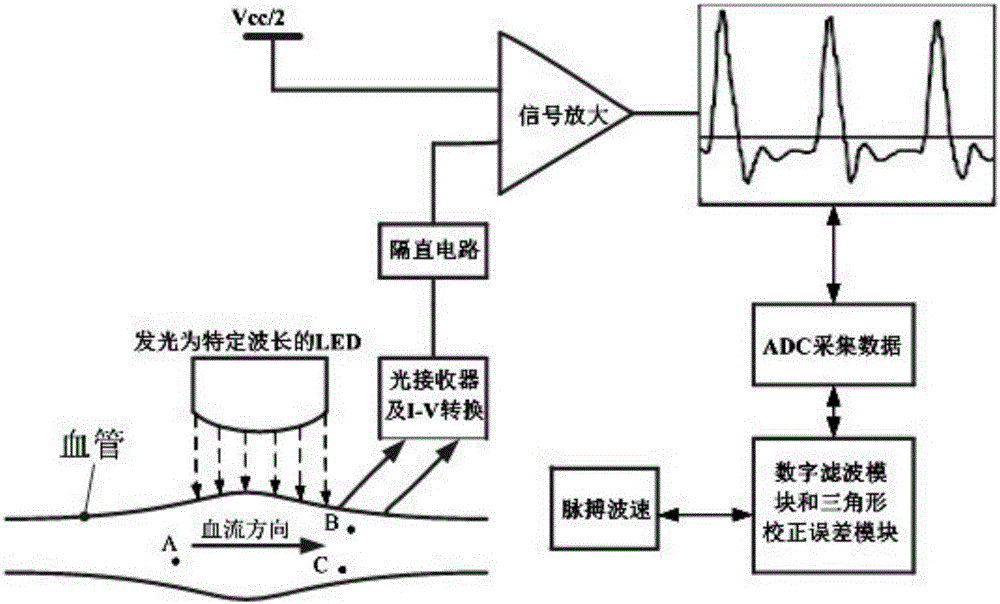
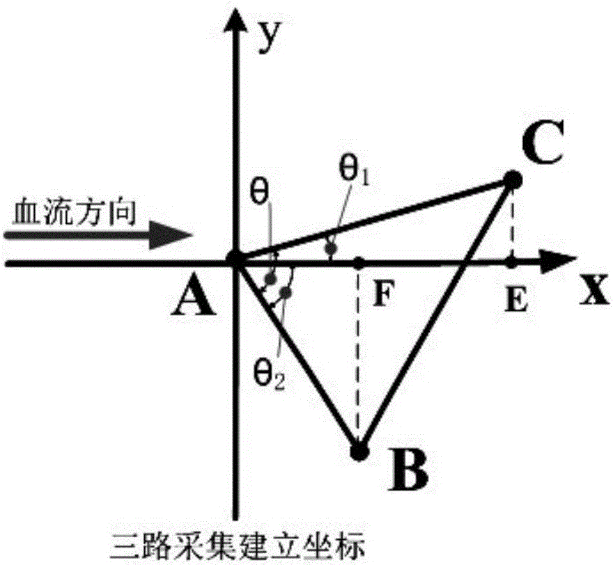
[0075] Embodiment 1: see Figure 1 to Figure 3 , the preset three-way LED irradiation module includes 3 LEDs, and the irradiation points are points A, B, and C respectively, and a device for measuring pulse wave velocity in a small range based on the light reflection method of the present invention is established.

[0076] Its measurement method is:

[0077] (1) Select the blood vessels that need to measure the pulse of the human body, and set up a three-way LED irradiation module, where point A is located at the upstream of the blood flow, and points B and C are located at the downstream of the blood flow. Placed in the direction of wrist radial artery blood flow;

[0078] (2) Use the three-way light receiving module to receive the reflected light of the three-way LED whose reflection intensity changes periodically with the pulse pulse, and perform photoelectric conversion on the reflected light, and convert the optical signal into a voltage signal; the receiving head of the...

Embodiment 2

[0095] Embodiment 2: The preset three-way LED irradiation module includes 4 LEDs, and the irradiation points are points A, B, C, and D respectively. A device for measuring pulse wave velocity in a small range based on the light reflection method of the present invention is established, wherein A is located upstream, and the rest are located downstream. The present invention can be divided into two triangles starting from A, ABC and ACD. At this time, two wave velocity data can be obtained by the above method.


PUM


Abstract

The invention discloses a device and a method for measuring pulse wave velocity in a small range based on a light reflection method. The method comprises: using three measuring points A, B, and C which are respectively on vertexes of an arbitrary triangle to detect pulse wave signals, after photovoltaic conversion and blocking amplification are performed on the three paths of signals, through an ADC, acquiring data and storing the data; after certain data size is acquired, performing zero phase-shift digital filtering on the acquired data strings; after zero phase-shift digital filtering processing, finding out moments corresponding to peak values of three paths of main wave crests, and meanwhile determining time difference of two wave crests; and combined with a geometric correction error method, calculating a pulse wave. The method can measure pulse wave velocity in a small area rang of a human body surface, and prevents discomfort of a tested person caused by a pressure sensor. A digital filtering method is used to overcome defects that an analog filter would cause phase shift error on the pulse wave. The device and the method are advantaged by high precision, simple operation, and real-time property, and the method provides convenience for portable and wearable design of a device.

Description

technical field [0001] The invention relates to a pulse wave velocity measuring device and method, in particular to a device and method for measuring pulse wave velocity in a small range based on a light reflection method. Background technique [0002] The aging population has become a common concern, and hypertension and cardiovascular disease have become a very challenging health problem, so better medical solutions are needed. In recent years, smart wearable products have been surging, but there are few wearable products that can measure blood pressure. Based on the close relationship between cardiovascular health and human blood pressure and pulse wave velocity, it is of great significance to measure pulse wave velocity. There have been relevant researches in this area in the last century, but there are very few practical products, and there are only a handful of wearable products. [0003] In 2013, Yang Gang and others developed a measurement device and method for pul...

Claims


Application Information

Patent Timeline
Patent Type & Authority Applications(China)
IPC IPC(8): A61B5/02A61B5/0285
CPCA61B5/0261A61B5/02007A61B5/0285
Inventor 王洪辉李展
Owner CHENGDU UNIVERSITY OF TECHNOLOGY
Learn More