Blade root for a turbine blade

A technology of turbine blades and turbine blades, which is applied to the supporting elements of blades, components of pumping devices for elastic fluids, non-variable-capacity pumps, etc. problems, to achieve the effect of short start-up time, fast load change, and minimization of the tendency of plastic deformation

Inactive Publication Date: 2016-11-09
SIEMENS AG
View PDF7 Cites 0 Cited by
  • Summary
  • Abstract
  • Description
  • Claims
  • Application Information

AI Technical Summary

Problems solved by technology

This leads to the fact that the turbine blade root no longer fits tightly at this point and becomes loose

Method used


Image

  • Blade root for a turbine blade
  • Blade root for a turbine blade
  • Blade root for a turbine blade

Examples


Embodiment Construction

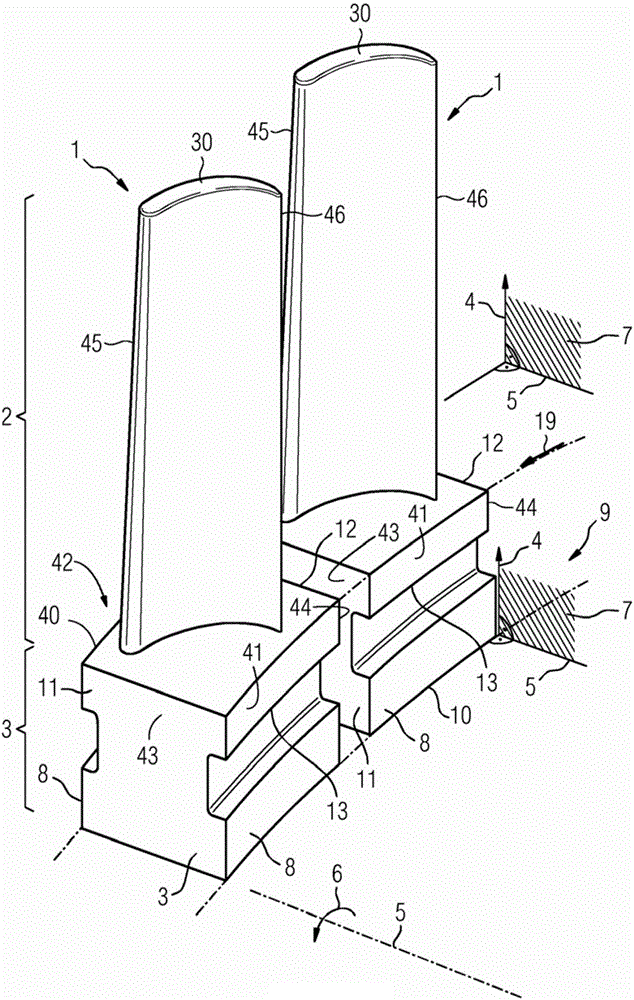
[0032] figure 1 A turbine blade 1 is shown. The turbine blade 1 can be a turbine guide blade or a turbine rotor blade. The turbine blade 1 has an airfoil 2 and a blade root 3 which are arranged along a blade axis 4 . The blade axis 4 corresponds substantially to the elongated configuration of the turbine blade 1 . The blade airfoil 2 is shaped and designed for installation in a fluid machine, in particular a steam turbine. The turbine blade 1 engages in a groove which is not shown in detail. A fluid machine, such as a steam turbine, has a rotor mounted rotatably about an axis of rotation 5 and a housing arranged around the rotor. The grooves are provided on the surface (not shown) in the rotor, the rotor being formed around the axis of rotation 5 . As a result, the rotor rotates in a direction of rotation 6 about the axis of rotation 5 . The blade axis 4 is here formed perpendicular to the axis of rotation 5 . The axis of rotation 5 and the blade axis 4 form a radius su...


PUM


Abstract

The invention relates to a turbine blade (1) with a blade (2), a blade root (3), and a cover plate (14) between the blade root (3) and the blade (2). The cover plate (14) has a parallelogram (42) with a front surface (40) and a rear surface (41) and a first bearing surface (43) and a second bearing surface (44). The blade (2) has a profiled design and a leading edge (45) and a trailing edge (46), said leading edge (45) pointing towards the front surface (40) and said trailing edge (46) pointing towards the rear surface (41). The front surface (40) has a curvature (20) in at least some sections in order to prevent a plastic deformation during operation.

Description

technical field [0001] The invention relates to a turbine blade having a blade body and a blade root, wherein the blade root and the blade body are formed along a blade axis, the blade axis being oriented perpendicularly to the axis of rotation, wherein the axis of rotation and the blade axis form a radial surface The blade root also has side surfaces which are formed substantially perpendicular to the radius surface. [0002] Furthermore, the invention relates to a method for producing an arrangement of a turbine blade in a groove of a turbomachine. Background technique [0003] The superordinate concept "fluid machinery" includes water turbines, steam and gas turbines, wind turbines, centrifugal pumps and compressors, and propellers. Common to all these machines is that they are used to extract energy from a fluid to drive other machines, or conversely to deliver energy to a fluid to increase the pressure of said fluid. [0004] A steam turbine as an embodiment of a flui...

Claims


Application Information

Patent Timeline
Patent Type & Authority Applications(China)
IPC IPC(8): F01D5/30F04D29/32
CPCF04D29/322F05D2230/642F05D2240/80F01D5/3038F05D2230/50
Inventor 阿尔明·德拉泽尔
Owner SIEMENS AG
Why Eureka
Try Eureka