
Dual-polarization dielectric resonator antenna unit and base station antenna

A dielectric resonator and antenna unit technology, applied in the field of mobile communication, can solve the problems of difficult feeding structure, low gain, and narrow working frequency band of the dielectric resonator unit, and achieve high gain, reduced section height, and simplified feeding structure Effect

Active Publication Date: 2016-11-09
SOUTH CHINA UNIV OF TECH +1
View PDF3 Cites 12 Cited by
  • Summary
  • Abstract
  • Description
  • Claims
  • Application Information

AI Technical Summary

Problems solved by technology

[0004] However, the design of the dielectric resonator antenna unit faces many difficulties, for example, the working frequency band is narrow, the gain is low, and the feeding structure of some forms of dielectric resonator unit is difficult to use in engineering practice, etc.
[0005] At present, although there are many researches on the invention of dielectric resonator antennas, they are all limited to one aspect or certain aspects, for example, limited to single-polarized or circular-polarized small antennas with only one or a few units, or Limited to X-band, Ku-band and other ultra-high frequency and extremely high-frequency millimeter wave bands that have not yet been applied in the field of civil communications, etc.
[0006] There are relevant academic papers on dual-polarized dielectric resonator antenna units, and it is proposed that the use of high-order modes of dielectric resonators not only expands the bandwidth of dielectric resonator antennas, but also improves the gain of the corresponding frequency band, but there are also obvious The defect, that is, the section height of the dielectric resonator unit is greater than a quarter of the wavelength, which is more than half of the height of the conventional antenna unit in the same frequency band.

Method used


Image

  • Dual-polarization dielectric resonator antenna unit and base station antenna
  • Dual-polarization dielectric resonator antenna unit and base station antenna
  • Dual-polarization dielectric resonator antenna unit and base station antenna

Examples


Embodiment 1

[0043] Please combine figure 1 , figure 2 , image 3 and Figure 4 , the dual-polarized dielectric resonator antenna unit 100 of the present invention (for convenience of description, hereinafter referred to as "antenna unit 100") includes a substrate 6, a dielectric resonator 3 and a director 1 sequentially connected from bottom to top.

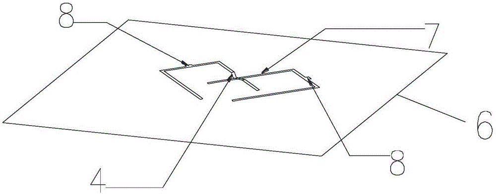
[0044] The substrate 6 is preferably a PCB (Printed Circuit Board, printed circuit board) substrate, its upper surface is provided with a ground plane, and the slit 5 corresponding to the two polarizations is etched in the ground plane; the lower surface of the substrate 6 A microstrip feeder 7 matching the slot is etched for connecting with an external feeding network (not shown) to feed the antenna unit 100 .

[0045] The dielectric resonator 3 is fixed on the upper surface of the substrate 6 and covers the gap.

[0046] The director 1 is fixed above the dielectric resonator 3 , and its projection on the substrate 6 covers the gap 5 ....

Embodiment 2

[0066] Please combine Figure 5 and Figure 6 , Embodiment 2 is similar to Embodiment 1, the difference is that another kind of slit 5 and a matching microstrip feeder 7 are provided on the substrate 6 .

[0067] The slit 5 includes first, second, third and fourth slits that are symmetrical to the center and perpendicular to each other between every two adjacent slits, and the first, second, third and fourth slits are connected to The distances between the centers of symmetry are equal, that is, the four slits are in a rotationally symmetrical relationship. The first, second, third, and fourth slits are preferably the same H-shaped slit, and the equivalent length of each H-shaped slit is the equivalent half-wavelength corresponding to the low-frequency center frequency to be designed, that is where λ 1 is the wavelength corresponding to the low-frequency central frequency of the desired design frequency band, and ε is the relative permittivity of the dielectric resonator 3...


PUM


Abstract

The invention provides a dual-polarization dielectric resonator antenna unit, and the dielectric resonator antenna unit comprises a substrate, a dielectric resonator and a director, wherein the substrate, the dielectric resonator and the director are sequentially connected from the bottom to the top. The upper surface of the substrate is provided with a grounding surface, and a gap is disposed in the grounding surface in an etching manner. The lower surface of the substrate is provided with a microstrip feed line which is matched with the gap and is used for feed. The projections of the dielectric resonator and the director on the substrate cover the gap. According to the embodiment of the invention, the dielectric resonator antenna unit meets the requirements of low profile and high gain of a dual-polarization dielectric resonator antenna unit. Moreover, a feed structure of the dielectric resonator antenna unit is symmetric, and is liable to assemble. In addition, the invention also discloses a base station antenna comprising the dielectric resonator antenna unit.

Description

technical field [0001] The invention relates to the field of mobile communication, in particular to a dual-polarized dielectric resonator antenna unit and a base station antenna. Background technique [0002] With the rapid development of mobile communication technology and the continuous expansion of the mobile communication market, people urgently need more miniaturized base station antennas, and also hope that the loss of base station antennas will be smaller and smaller to reduce energy consumption. [0003] The dielectric resonator antenna is one of the technical development directions for base station antenna miniaturization and energy saving requirements. On the one hand, the use of high dielectric constant materials can greatly shorten the equivalent wavelength of electromagnetic waves in space. The dielectric resonator antenna unit designed using this basic principle is much smaller than the conventional base station antenna unit; on the other hand, in the high freq...

Claims


Application Information

Patent Timeline
Patent Type & Authority Applications(China)
IPC IPC(8): H01Q1/36H01Q1/48H01Q1/50
CPCH01Q1/36H01Q1/48H01Q1/50
Inventor 李剑荣李明超赖展军
Owner SOUTH CHINA UNIV OF TECH
Learn More