
Non-deflection rod type high-frequency tuning mass damper

A technology of tuning mass and deflection rod, applied in the direction of protective buildings/shelters, building components, building structures, etc., can solve the problem of unstable working attitude of auxiliary mass, unable to guarantee the balance of auxiliary mass, working frequency and design Frequency deviation and other problems, to achieve the effect of large natural frequency range, optimized lateral stiffness and vertical stiffness, and improved service life

Active Publication Date: 2016-11-09
GUANGZHOU METRO GRP CO LTD +2
View PDF12 Cites 2 Cited by
  • Summary
  • Abstract
  • Description
  • Claims
  • Application Information

AI Technical Summary

Problems solved by technology

However, in this type of structure, since the connecting rod is set at the center of the auxiliary mass, the anti-eccentric torsion accuracy is high, and the balance of the auxiliary mass cannot be guaranteed. The working attitude of the auxiliary mass is not stable, and its posture during motion is often not only There is movement and torsion at the same time, which cannot achieve precise frequency modulation, resulting in a deviation between the actual operating frequency of the system and the design frequency, thus affecting the final vibration reduction effect
In order to improve stability, it is generally necessary to increase the guiding structure. On the one hand, the complexity of the structure is increased, and the cost is increased; powerful

Method used


Image

  • Non-deflection rod type high-frequency tuning mass damper
  • Non-deflection rod type high-frequency tuning mass damper
  • Non-deflection rod type high-frequency tuning mass damper

Examples


Embodiment 2

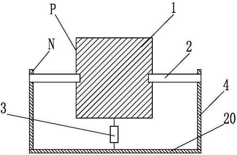
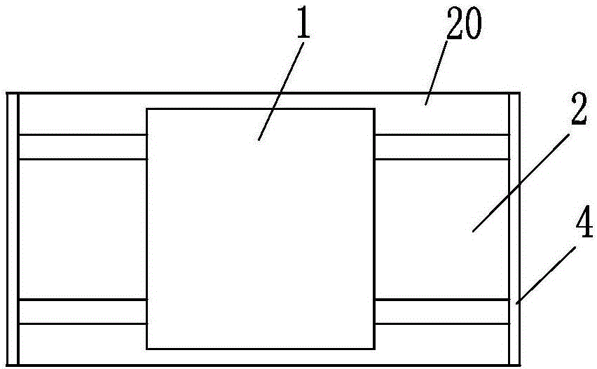
[0046] like Figure 4 , Figure 5 The non-deflection rod-type high-frequency tuning mass shock absorber of the present invention shown includes a mass block 1, an elastic element 2 and a damping element 3. The elastic element 2 is composed of an elastic rod made of two steel rods, and the two elastic rods are The ends are respectively supported on the bracket 4 and welded and fixed together with the bracket 4. The mass block 1 is arranged on the elastic rod, and the elastic rod penetrates the mass block 1 and is welded and fixed together with the mass block. The resultant force at least passes through the center of mass of the mass block or near the center of mass in the vertical component force; the damping element 3 is arranged under the mass block 1, and the damping element 3 is specifically a small-hole throttling damper, one end of which is connected to the mass block 1, and the other One end is connected with the connecting bottom plate 20 of the bracket 4; a frequency ...

Embodiment 3

[0051] like Figure 7 and Figure 8 The difference between the deflection-rod-type high-frequency tuning mass damper of the present invention shown in Embodiment 2 is that the elastic element 2 is composed of an aluminum alloy elastic rod with a rectangular cross-sectional shape. In order to prevent the axial movement of the elastic rod Moving, the two ends of the corresponding elastic rods on the outside of the bracket 4 are respectively provided with stoppers 5 and fasteners 6; in addition, the non-deflection rod type high-frequency tuned mass damper described in this example also includes a frequency adjustment device, the The frequency adjustment device includes two frequency adjustment bushings 7. The frequency adjustment bushings 7 are located on both sides of the mass block 1 and are arranged symmetrically. They are sleeved and fixed on the elastic rod by fastening screws 8. fixed on the elastic rod; in addition, the elastic element 3 includes two elastic shear dampers...

Embodiment 4

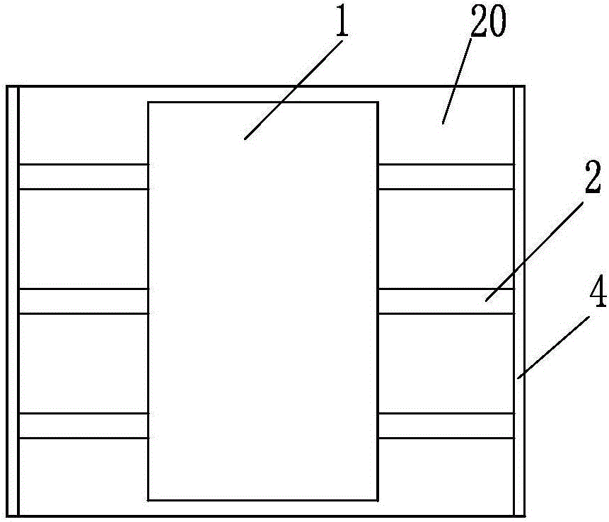
[0057] like Figure 9 and Figure 10 The difference between the non-deflection rod type high-frequency tuning mass damper of the present invention and the second embodiment is that the elastic element 2 includes four elastic rods, and the outer surface of the middle part of the elastic rods is provided with threads; in addition, both sides of the mass block 1 are fixed The ear plate 9 is set, and the elastic rod is set through the ear plate 9 to realize the support of the mass block 1; thirdly, in order to prevent the elastic rod from moving axially, stoppers 5 are respectively arranged on the outside of the bracket 4 corresponding to the two ends of the elastic rod and fasteners 6; fourthly, a lock nut 10 and a frequency adjustment device are arranged on the elastic rod, and the frequency adjustment device includes frequency adjustment sleeves 32 arranged in pairs, and the frequency adjustment sleeves 32 are specifically thickened The locking nuts are arranged symmetrically ...


PUM


Abstract

The invention relates to a non-deflection rod type high-frequency tuning mass damper and belongs to the technical field of civil engineering structure damping. The problems that the occupied space is large, the applicability is not high, the cost is high, and precise frequency modulation cannot be achieved in the prior art are solved through the non-deflection rod type high-frequency tuning mass damper. The non-deflection rod type high-frequency tuning mass damper comprises a mass block, an elastic element and a damping element. The elastic element comprises at least two elastic rods. The two ends of the elastic rods are supported on a bracket, and the mass block is connected with the elastic rods; or, one ends of the elastic rods are supported on the bracket, and the other ends of the elastic rods are connected with the mass block. When all the elastic rods work, the component force of the dynamic restoring force resultant force at least in the perpendicular direction passes the mass center of the mass block or passes the position near the mass center. The damping element is directly arranged on the surfaces of the elastic rods or is connected with the mass block. The non-deflection rod type high-frequency tuning mass damper is higher in applicability and performance price ratio, capable of being widely used for high-frequency vibration control over underground track beds and other structures and very wide in market application prospects.

Description

technical field [0001] The invention belongs to the technical field of vibration reduction of civil engineering structures, and in particular relates to a tuned mass vibration damper for controlling high-frequency vibrations of building structures. Background technique [0002] A large number of engineering practices have proved that the tuned mass damper (also called mass tuned damper in the literature, or mass tuned damper, also referred to as TMD in this paper) is an effective vibration control device, and its natural frequency is adjusted to close to the natural frequency of the main structure, and then installed on the main structure. When the main structure is disturbed by the exciting force and vibrates, the resonance of the mass-tuned damper is caused, and the vibration inertia force of the tuning mass is used to react against the structure itself, thereby offsetting the exciting force and reducing the structural response. In order to maximize the damping effect of ...

Claims


Application Information

Patent Timeline
Patent Type & Authority Applications(China)
IPC IPC(8): E04B1/98E04H9/02
CPCE04H9/02E04H9/0215
Inventor 尹学军谭文刘兴龙邹东刘浪静黄红东刘焕欣党红玲刘铁民王建立孔祥斐王建高星亮陈常福
Owner GUANGZHOU METRO GRP CO LTD
Learn More