
Single-tube resolution testing device of low-light level image intensifier

A low-light image intensifier and resolution technology, which is used in optical instrument testing, machine/structural component testing, measuring devices, etc., to achieve the effects of humanized operation, saving testing time, and simple and reasonable structural design.

Inactive Publication Date: 2016-10-26
NANJING UNIV OF SCI & TECH
View PDF7 Cites 3 Cited by
  • Summary
  • Abstract
  • Description
  • Claims
  • Application Information

AI Technical Summary

Problems solved by technology

In China, with the continuous expansion of the night vision technology market, the research on the resolution test of the image tube is getting more and more popular, but there is no single-tube resolution test equipment specifically for the ultra-second-generation low-light image intensifier.

Method used


Image

  • Single-tube resolution testing device of low-light level image intensifier
  • Single-tube resolution testing device of low-light level image intensifier
  • Single-tube resolution testing device of low-light level image intensifier

Examples


Embodiment Construction

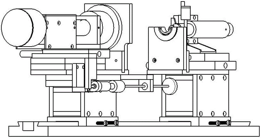
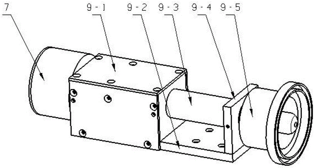
[0011] In combination with Fig. 1(a)(b), a super second-generation low-light image intensifier image tube single-tube test device includes an optical rail 1, and the left sliding base connected to the optical rail 1 includes a left slider 2 and a left support seat 3. The right sliding base 19; the left mechanical adjustment module connected to the top of the support base 3 includes from bottom to top: image tube clamping displacement adjustment platform 4, left transition plate 5, displacement adjustment module 6 in the X-axis direction, and Y-axis The displacement adjustment platform 8; the light source uniform attenuation and object image projection module 9 connected to the Y-axis displacement adjustment platform 8; the light source 7 connected to the light source uniform attenuation and object image projection module 9; the left image tube fixture connected to the left transition plate 5 10; the right transition plate 18 connected to the right sliding base 19; the right mec...


PUM


Abstract

The invention provides a single-tube resolution testing device of a super-second-generation low-light level image intensifier. The device comprises an optic guide rail, a sliding pedestal, a mechanical adjusting module, a light source, a light source uniform attenuation and objective image projection module, an image tube clamp, and a monocular microscope module. The sliding pedestal, the mechanical adjusting module, and the image tube clamp are divided into left and right parts including a left sliding pedestal and a right sliding pedestal, a left mechanical adjusting module and a right mechanical adjusting module, and a left image tube clamp and the right image tube clamp. The optic guide rail, the sliding pedestal, and the mechanical adjusting module are arranged from bottom to top; the light source, the light source uniform attenuation and objective image projection module, the left image tube clamp, and the monocular microscope module are arranged on the mechanical adjusting module successively from left to right in a central coaxial mode. All parts are connected by bolts. The left sliding pedestal and the right sliding pedestal enable the parts arranged on the left sliding pedestal and the right sliding pedestal to move or locked on the optical guide rail.

Description

technical field [0001] The invention relates to a low-light test technology, in particular to a low-light image intensifier single-tube resolution test transposition. Background technique [0002] Resolution is one of the important performance parameters of low-light image intensifiers. Currently, the test method for resolution is mainly based on human eye observation. In China, with the continuous expansion of the night vision technology market, the research on the resolution test of the image tube is getting more and more popular, but there is no single-tube resolution test equipment specifically for the ultra-second-generation low-light image intensifier. Contents of the invention [0003] The object of the present invention is to provide a single-tube resolution test device of a super-second-generation low-light image intensifier, which can realize the resolution test of a single-tube image tube of a super-second-generation low-light image intensifier. The adjustment ...

Claims


Application Information

Patent Timeline
IPC IPC(8): G01M11/04
CPCG01M11/04
Inventor 邱亚峰宋诚鑫
Owner NANJING UNIV OF SCI & TECH
Learn More