
Energy-saving and environment-friendly two-circuit parallel type smoke waste heat recycling device and method

A flue gas waste heat, energy saving and environmental protection technology, applied in the direction of reduction of greenhouse gases, climate sustainability, lighting and heating equipment, etc., can solve certain effects of combustion conditions, easily damaged waste heat recovery devices, inconvenient boiler maintenance and cleaning, etc. problems, to achieve the effect of improving heat utilization, improving dust removal effect, improving stability and sealing

Inactive Publication Date: 2016-10-26
ZHENJIANG CITY POWER STATION AUXILIARY MACHINERY PLANT
View PDF13 Cites 3 Cited by
  • Summary
  • Abstract
  • Description
  • Claims
  • Application Information

AI Technical Summary

Problems solved by technology

The waste heat recovery device used in the prior art is usually installed between the boiler exhaust port and the chimney outlet, but the disadvantage of this method is that the boiler flue gas waste heat device has a large resistance to the flue gas discharged from the boiler, and the combustion inside the boiler Conditions will have a certain impact; it is not convenient to maintain and clean the boiler flue gas waste heat recovery device directly in series between the boiler exhaust port and the chimney outlet, and the maintenance and cleaning of the waste heat recovery device still requires the gas The boiler can only be carried out when the boiler is shut down; the flue gas will be mixed with a lot of dust, which will be absorbed in the waste heat recovery device for a long time, which is easy to damage the waste heat recovery device. If it is treated with a dust collector, although the particles in the flue gas can be purified, there are fine particles If the temperature of the flue gas is lowered below the dew point, the condensed water will adhere the particles in the flue gas to the surface of the heat exchanger and block the flue

Method used


Image

  • Energy-saving and environment-friendly two-circuit parallel type smoke waste heat recycling device and method

Examples


Embodiment Construction

[0026] The specific embodiments of the present invention will be further described below in conjunction with the accompanying drawings.

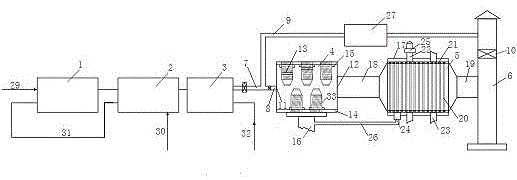
[0027] An energy-saving and environment-friendly double-circuit parallel flue gas waste heat recovery device, comprising a heating furnace 1, a heat exchanger 2, a boiler 3, a dust settling chamber 4, a waste heat recovery device 5 and a vertical chimney 6, wherein the heat exchange The two ends of the device 2 are respectively connected with the heating furnace 1 and the boiler 3, and the boiler 3 is provided with a flue gas output pipe 7, and the flue gas output pipe 7 is respectively connected with a first branch pipe 8 and a second branch pipe 9;

[0028] One side of the dust settling chamber 4 is provided with a smoke inlet 11, and the other side is provided with a smoke outlet 12. The smoke inlet 11 is connected to the first branch pipe 8, and several guide pipes are arranged in the dust settling chamber 4. Flow plate 33, the plurality...


PUM


Abstract

The invention relates to an energy-saving and environment-friendly two-circuit parallel type smoke waste heat recycling device and method. The device comprises a heating furnace, a heat exchanger, a boiler, a dust settling chamber, a waste heat recoverer and a vertical chimney. The boiler is provided with a smoke output pipe which is connected with a first distributing branch pipe and a second distributing branch pipe, a plurality of guide plates are arranged in the dust settling chamber and provided with holes, and a plurality of heat exchange pipes are arranged in the waste heat recoverer. A tube pass inlet is formed in the top of the waste heat recoverer, the bottom of the waste heat recoverer is provided with a tube pass outlet and a condensate outlet, and the second distributing branch pipe is provided with a dust remover. Smoke waste heat can be purified, the heat utilization rate is increased, and meanwhile environment pollution is prevented through dust purification.

Description

technical field [0001] The invention relates to an energy-saving and environment-friendly dual-circuit parallel flue gas waste heat recovery device and method, and belongs to the technical field of energy recovery and utilization equipment. Background technique [0002] At present, in the face of the tense world energy situation, domestic and foreign countries have been researching and developing alternative new energy sources. At the same time, they are also paying attention to the recycling of energy in the process of energy saving and emission reduction. In 2012, the State Council officially issued the "Ten The Second Five-Year Plan specifically clarified the key projects of energy conservation and emission reduction in the "Twelfth Five-Year Plan", and focused on the utilization of residual pressure and waste heat in energy-saving renovation projects. With the further development of energy-saving work, various new energy-saving and advanced furnace types are becoming mor...

Claims


Application Information

Patent Timeline
IPC IPC(8): F23J15/00F23J15/06F23J15/02
CPCF23J15/006F23J15/022F23J15/06Y02E20/30
Inventor 王爽严俊杰虞永川张凯
Owner ZHENJIANG CITY POWER STATION AUXILIARY MACHINERY PLANT
Learn More