
Rectangular concrete-filled steel tube column restrained by rib-perforating pull bars

A technology of rectangular steel tube and concrete column, applied in the direction of column, pier column, pillar, etc., can solve the problems of limited bearing capacity of rectangular steel tube concrete column, weak out-of-plane deformation capacity of stiffener restraint, weak lateral restraint force, and tension connection. , to achieve the effect of improving the lateral restraint capacity, delaying or avoiding slippage, and continuous and uniform restraint action

Inactive Publication Date: 2016-10-26
HENAN POLYTECHNIC UNIV
View PDF11 Cites 3 Cited by
  • Summary
  • Abstract
  • Description
  • Claims
  • Application Information

AI Technical Summary

Problems solved by technology

This type of stiffener has a weak ability to restrain deformation outside the surface, and the failure of the bond with the concrete in the later stage of loading will easily lead to detachment. In order to delay or prevent the deformation of the middle part of the side, a larger stiffness ratio of the rib plate is required, and more steel is consumed.
Moreover, the stiffeners failed to form a circumferential constraint on the core concrete, and the lateral constraint force was weaker than that of the opposite-tension connection of the restraint tie rods. Although it can delay the occurrence of local buckling to a certain extent, the improvement of the bearing capacity of the rectangular CFST column is limited.

Method used


Image

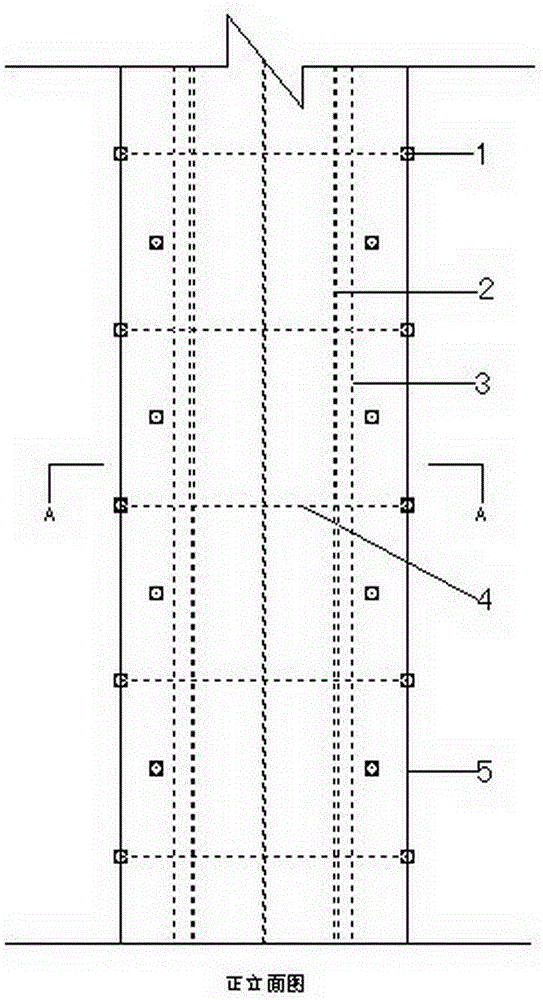
  • Rectangular concrete-filled steel tube column restrained by rib-perforating pull bars
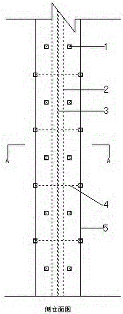
  • Rectangular concrete-filled steel tube column restrained by rib-perforating pull bars
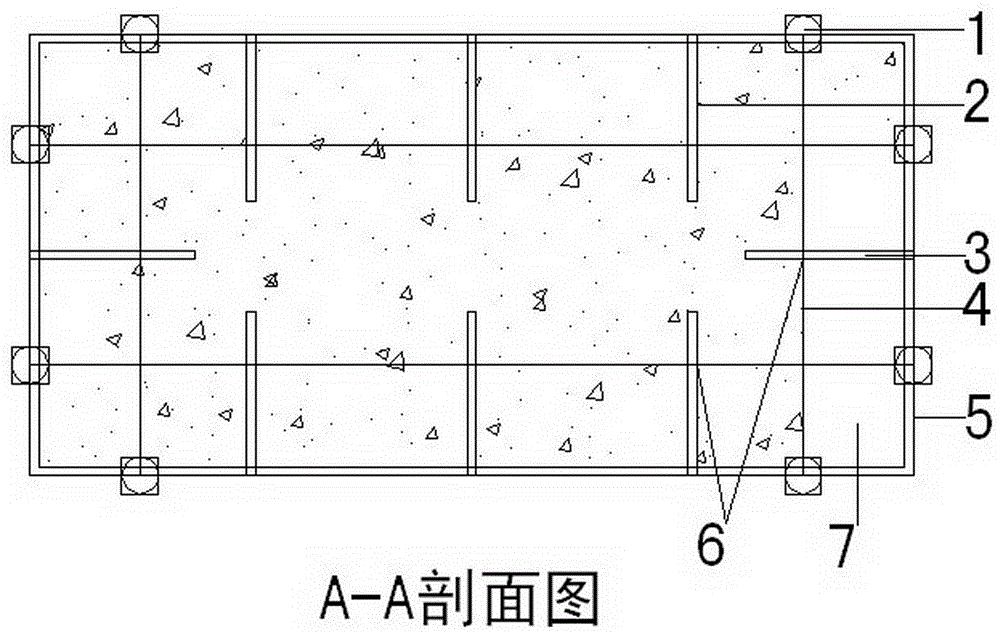
  • Rectangular concrete-filled steel tube column restrained by rib-perforating pull bars

Examples


Embodiment 1

[0026] The manufacturing steps of a rectangular steel tube concrete column constrained by perforated rib tie rods are as follows:

[0027] (1) Determine the strength, size and position of rectangular steel pipes, tie rods and opening stiffeners according to the requirements of the design drawings;

[0028] (2) Rectangular steel pipes 5, perforated stiffeners, and tie rods 4 for making rectangular steel pipe concrete columns;

[0029] (3) Measure the layout position of the positioning tie rod 4, and drill a hole at the position where the tie rod 1 of the rectangular steel pipe of the steel tube concrete column passes through;

[0030] (4) The opening stiffener is welded to the wall of the rectangular steel pipe by means of welding;

[0031] (5) Install the tie rod 4 through the opening stiffener in the drilled hole of the rectangular steel pipe, and use perforated plug welding or bolt connection;

[0032] (6) Pour concrete into rectangular steel pipes and perform maintenance ...


PUM


Abstract

The invention discloses a rectangular concrete-filled steel tube column restrained by rib-perforating pull bars. The rectangular concrete-filled steel tube column comprises stiffening ribs, pull bars, a rectangular steel tube and concrete. The stiffening ribs are strip-shaped steel plates with thickness identical to the thickness of the steel tube. The stiffening ribs are provided with holes at positions where the pull bars pass through, and the holes are of the exact size that allows the pull bars to pass through. The stiffening ribs are uniformly arranged at the internal circumference of the wall of the steel tube, perpendicular to the steel tube wall and connected with the steel tube wall in a welding manner. The pull bars are common pull bars or steel bars, vertically penetrate the tube wall of the rectangular steel tube and are staggerly arranged at proper intervals along the long side and short side of the column. The end parts of the pull bars are connected with the steel tube wall through welding or by bolts. According to the invention, the stiffening ribs are cooperated with the restraining pull bars, so bonding slip between the steel tube wall and concrete can be delayed, local outer surface deformation of the steel tube wall can be alleviated, the lateral rigidity of the steel tube wall can be improved, and the steel tube wall has improved capacity in resisting local bending and restraining effect on core concrete; and thus, the rectangular concrete-filled steel tube column has improved bearing capacity and ductility.

Description

technical field [0001] The invention relates to the technical field of building structures, in particular to a rectangular steel tube concrete column constrained by perforated rib tie rods. Background technique [0002] Rectangular concrete-filled steel tube columns have unique features incomparable to circular concrete-filled steel tube columns in engineering applications, such as easy fabrication of steel tubes, easy handling of connections with beams, convenient construction, easy compliance with building plane requirements, relatively open cross-section and large moment of inertia, suitable for As a bending member and other advantages, it has increasingly attracted people's attention in engineering practice. [0003] For rectangular CFST, since the confinement effect of the steel pipe on the core concrete is mainly concentrated in the corners, and the confinement effect in the middle of the four sides is almost non-existent, so the overall confinement effect of the steel...

Claims


Application Information

Patent Timeline
IPC IPC(8): E04C3/34
CPCE04C3/34
Inventor 郑新志
Owner HENAN POLYTECHNIC UNIV
Learn More