
Waste gas absorption tower and waste gas absorption method

An absorption tower and waste gas technology, applied in separation methods, chemical instruments and methods, gas treatment, etc., can solve the problems of incomplete absorption of waste gas and easy occurrence of circulation, so as to ensure the gas-liquid contact time, improve the removal rate, and improve the waste gas. The effect of processing efficiency

Inactive Publication Date: 2016-10-26
广州益方田园环保股份有限公司
View PDF7 Cites 6 Cited by
  • Summary
  • Abstract
  • Description
  • Claims
  • Application Information

AI Technical Summary

Problems solved by technology

[0004] The invention proposes an exhaust gas absorption tower and its exhaust gas absorption method, which solves the problem of incomplete exhaust gas absorption and easy circulation in the prior art

Method used


Image

  • Waste gas absorption tower and waste gas absorption method
  • Waste gas absorption tower and waste gas absorption method

Examples


Embodiment 1

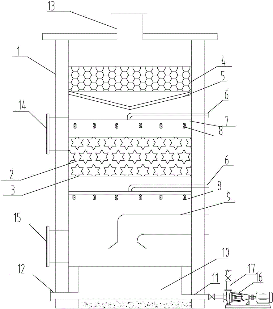
[0028] The structure diagram of the present invention is as figure 1 As shown, the exhaust gas absorption tower of the present invention includes an absorption tower tower body 1, a packing layer 2, a packing demister 4, a V-shaped tube type demister 5, an absorption liquid inlet pipe 6, a water distribution nozzle 8, an inlet Air pipe 9, circulating water pool 10, circulating pool outlet pipe 11, waste liquid discharge pipe 12, air outlet pipe 13, discharge port 14, inlet hole 15, absorption liquid circulating spray pump 16, water distribution nozzle 8 installed on the upper and lower layers The water distribution pipe 7, the water distribution pipe 7 is connected with the circulating liquid inlet pipe 6, the lower water distribution nozzle 8 is located near the entrance of the waste gas inlet pipe 9, the upper water distribution nozzle 8 is located near the top of the packing 2, and the liquid outlet pipe of the circulating pool 10 is connected to the circulating spray The s...

Embodiment 2

[0031] Like the waste gas absorption tower in Example 1, the tower body 1 can be square or other shapes with steel concrete as the main structure, which can be flexibly selected according to the site.

[0032] The working principle of the present invention is as follows: the exhaust gas enters the interior of the tower body 1 through the intake pipe 9 after dust removal, and the exhaust gas is first sprayed downward toward the circulating pool 10, and after being buffered, it is evenly upward, and is sprayed with the primary water distribution nozzle 8. The absorption liquid is in reverse contact. After the primary pretreatment, the waste gas enters the packing 2 through the stainless steel grid 3. At the same time, the secondary water distribution nozzle 8 continuously sprays the liquid to the packing 2. In the packing 2, the waste gas fully contacts with the absorption liquid, and the waste gas After the pollutants in the waste gas are absorbed by the absorption liquid, they ...


PUM


Abstract

The invention provides a waste gas absorption tower. The waste gas absorption tower comprises an adsorption tower body and a tower body external connection device, wherein the adsorption tower body adopts a hollow structure made of a steel concrete material, a gas outlet pipe is arranged on the upper end surface of the adsorption tower body, and a circulating water tank is arranged at the bottom of the adsorption tower body and connected with the tower body external connection device; a primary spraying layer and a secondary spraying layer arranged below the primary spraying layer in parallel are arranged in the middle of the adsorption tower body, and the spraying layers are adsorption layers; demisting layers are arranged at the upper part in the adsorption tower body; a waste gas inlet pipe is inserted into the lower part in the adsorption tower body. A treatment process is simple and convenient to operate, limitation of materials to process parameters is eliminated, and the pollutant removal efficiency and the demisting effect of the waste gas are improved.

Description

technical field [0001] The invention relates to the field of waste gas absorption, in particular to a waste gas absorption tower and a waste gas absorption method thereof. Background technique [0002] Food organic waste gas contains volatile organic compounds such as aromatic hydrocarbons and aldehydes, and the resulting odor seriously affects the surrounding environment. For most of the organic waste gas from the food industry that only contains aromatic hydrocarbons or aldehydes that are soluble in liquids, the absorption method has become a common method for this type of waste gas treatment because of its simple equipment, low cost and good treatment effect. [0003] At present, the commonly used treatment device in the food organic waste gas absorption system is a spray absorption tower based on polypropylene (PP) material, including the tower body, a layer of spray device and a demisting area are installed on the top of the tower inner cavity, and the middle and upper ...

Claims


Application Information

Patent Timeline
IPC IPC(8): B01D53/18
CPCB01D53/18B01D53/1487B01D2257/7027B01D2257/708
Inventor 田永卢玲玲马志国郭键勇
Owner 广州益方田园环保股份有限公司
Learn More