Medical image processing device and medical image processing method
A medical image and processing device technology, applied in the field of medical image processing device and medical image processing, can solve the problems of unsuitable micro tube structure, low detection accuracy, loss of capillary veins, etc.
- Summary
- Abstract
- Description
- Claims
- Application Information
AI Technical Summary
Problems solved by technology
Method used
Image

Examples
Embodiment approach 1
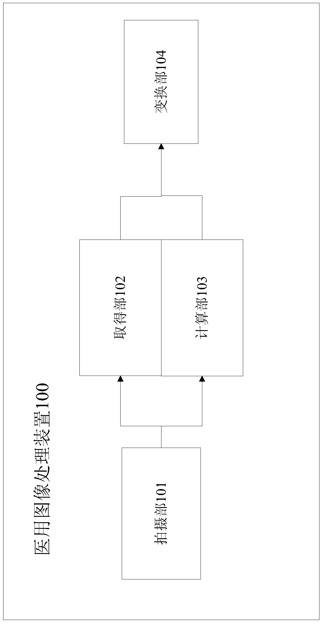
[0032] figure 1 It is a block diagram showing the medical image processing apparatus according to Embodiment 1 of the present invention.
[0033] Such as figure 1 As shown, the medical image processing device 100 includes an imaging unit 101 , an acquisition unit 102 , a calculation unit 103 , and a conversion unit 104 .
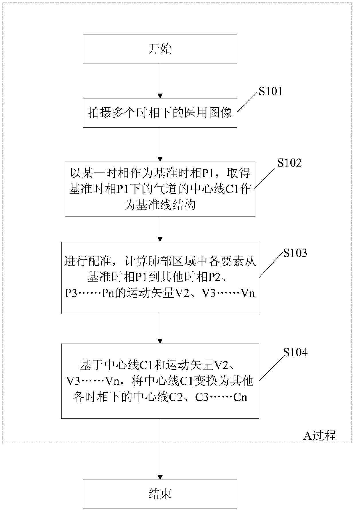
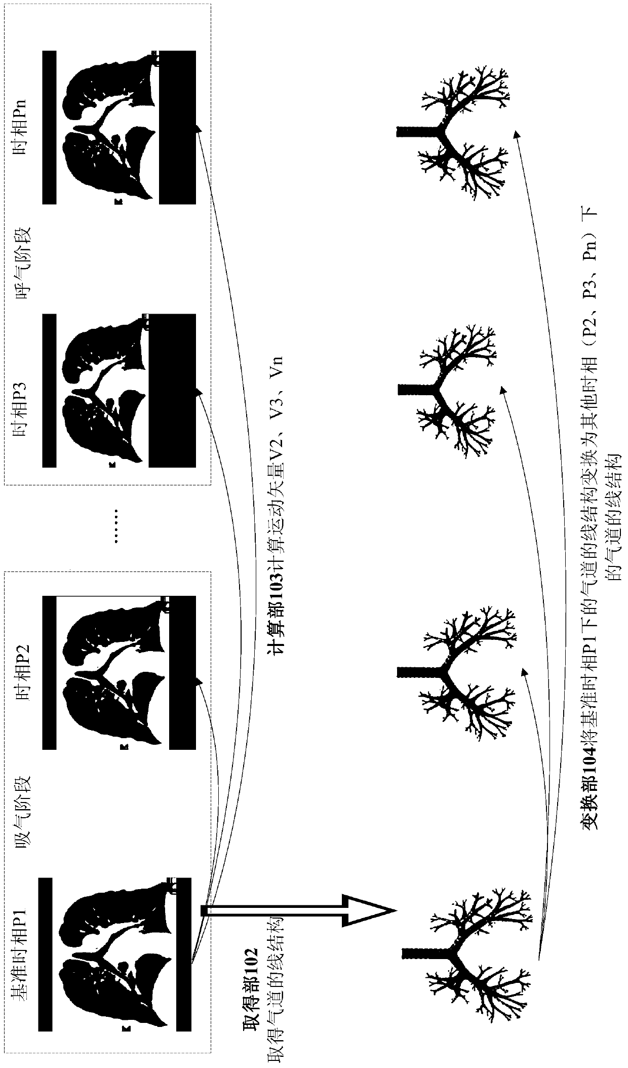
[0034] The imaging unit 101 images an object to be inspected to obtain a plurality of time-series medical images of the object. Taking one respiratory cycle as an example, the plurality of medical images are a plurality of medical images captured in each phase during the period from the beginning of the inhalation phase to the end of the exhalation phase. The medical image includes a region of interest to an operator as a region of interest. The region of interest in this embodiment is the lung region, but is not limited to the lung region.
[0035] The acquisition unit 102 takes a certain time phase in the time series as the reference time phase P1, and...
Embodiment approach 2
[0057] Image 6 It is a block diagram showing the medical image processing apparatus according to Embodiment 2 of the present invention. Such as Image 6 As shown, in addition to the imaging unit 101, the acquisition unit 102, the calculation unit 103, and the conversion unit 104 in the medical image processing device 100, the medical image processing device 200 in Embodiment 2 also includes: an attention region extraction unit 205 and a determination unit 206. Among them, the ROI extraction unit 205 is not essential and can be omitted. Components assigned the same reference numerals in the drawings are the same as those in the first embodiment. Only differences will be described below, and descriptions of the same parts will be omitted.
[0058] The region-of-interest extraction unit 205 extracts a region of interest to the observer, such as a lung region, from the constituent elements of the medical image captured by the imaging unit 101 , and uses the extracted region a...
Embodiment approach 3
[0074] Figure 8 It is a block diagram showing the medical image processing apparatus according to Embodiment 3 of the present invention.
[0075] Such as Figure 8 As shown, Embodiment 3 includes an imaging unit 301 , an acquisition unit 302 , a calculation unit 303 , a conversion unit 304 , and a comparison unit 305 . Embodiment 3 differs from Embodiment 1 in that the acquisition unit 302, calculation unit 303, and conversion unit 304 in Embodiment 3 are modifications of the acquisition unit 102, calculation unit 103, and conversion unit 104 in Embodiment 1. The comparison unit 305 is a part added to that of the first embodiment. Only the different parts are described below.
[0076] In Embodiment 3, in order to increase the accuracy of the comparison result by the comparison unit 207, image processing is performed using a mask covering the entire trachea and bronchi as a line structure instead of the central line of the trachea and bronchi in Embodiment 1. However, Imag...
PUM
 Abstract
Description
Claims
Application Information
 - R&D
- Intellectual Property
- Life Sciences
- Materials
- Tech Scout
- Unparalleled Data Quality
- Higher Quality Content
- 60% Fewer Hallucinations
Browse by: Latest US Patents, China's latest patents, Technical Efficacy Thesaurus, Application Domain, Technology Topic, Popular Technical Reports.
© 2025 PatSnap. All rights reserved.Legal|Privacy policy|Modern Slavery Act Transparency Statement|Sitemap|About US| Contact US: help@patsnap.com