


Quick Research
Generate reliable direction feasibility study reports for your R&D in just a few steps.

Technical Q&A
Discover and master advanced knowledge NOW. Basics, ideas, possibilities, all at once.

Find Solutions
As an expert in R&D theories, this can generate solutions to your technical problems instantly.

Evaluate Feasibility
Analyze your overall solution with one click, know your potential R&D risks in advance.

Monitor Landscape
Get weekly tech updates, stay abreast of the latest tech innovations and key insights.
Built-in safety socket
A safety socket, built-in technology, applied in the direction of coupling device, base/housing, connecting device parts, etc., to achieve high safety, avoid electric shock, and avoid contact
- Summary
- Abstract
- Description
- Claims
- Application Information
AI Technical Summary
Problems solved by technology
Method used
Image

Examples
Embodiment 1
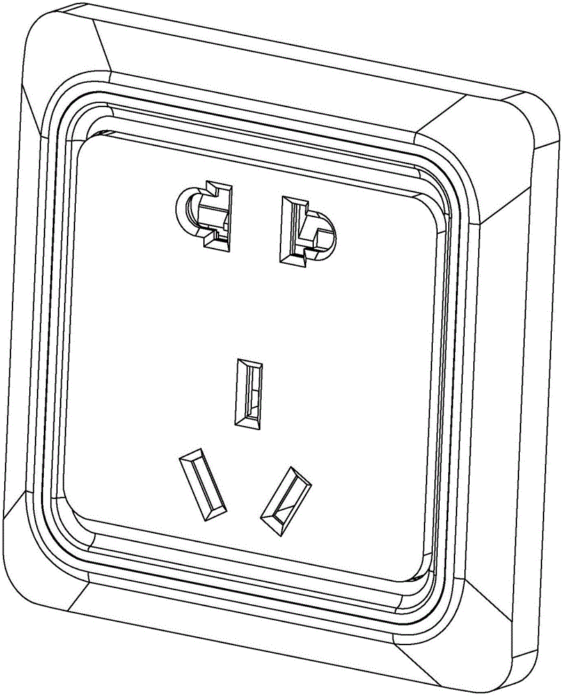
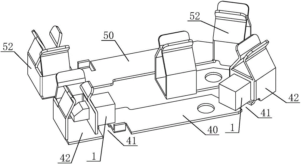
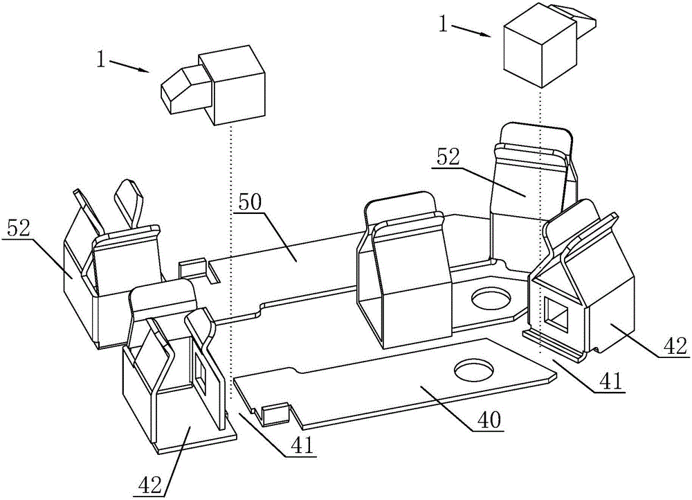
[0037] Such as Figures 1 to 9 The shown built-in safety socket includes a conductive socket, the conductive socket includes a live wire socket and a neutral wire socket, the live wire socket includes a live wire connecting plate 40 and a live wire slot cover 42, the neutral wire socket includes a zero There is a gap 41 between the live wire connecting plate 40 and the live wire slot cover 42, and the gap 41 is provided with a trigger for controlling the connection between the live wire connecting plate 40 and the live wire slot cover 42. The switch assembly 1 ; the trigger switch assembly 1 is located on the bottom surface of the live wire connecting board 40 .
[0038] The trigger switch assembly 1 is mainly used to control the connection between the live wire slot cover 42 and the live wire connecting plate 40. When the first and second terminals of the trigger switch assembly 1 connect the live wire slot cover 42 and the live wire connecting plate 40, the socket can be ene...
Embodiment 2
[0058] The difference between this embodiment and the first embodiment is that the second contact part 110 is a metal ring with a slope, the slope of the metal ring faces the rear end of the movable contact 31 , the protrusion 310 is ring-shaped, and the movable contact 30 is in the shape of a truncated cone.
[0059] The corresponding effects are as follows: firstly, the annular inclined surface of the metal ring forms a tapered surface, and the second contact portion 110 can increase the contact area with the convex portion 310, effectively avoiding poor contact and improving safety.
[0060] Secondly, the conical surface of the metal ring cooperates with the annular convex portion 310 to make the convex portion 310 concentric with the metal ring to ensure the concentricity of the two, so that the top of the contact can be accurately aligned with the arc-shaped contact portion of the first contact portion 100 1001, to avoid poor contact when misaligned.
Embodiment 3
[0062] The difference of this embodiment relative to Embodiment 1 is that the neutral line socket is provided with the same trigger switch assembly 1 as the live wire socket, and the neutral line connection plate 50 and the neutral line slot cover 52 are separated to leave a gap for controlling The trigger switch assembly 1 connecting the neutral line connection plate 50 and the neutral line slot cover 52 is arranged at the gap 51, and the first connection terminal 10 and the second connection terminal 11 of the trigger switch assembly 1 are connected to the neutral line slot cover 52 and the neutral line connection respectively. Board 50 is connected.
[0063] The function of the trigger switch assembly 1 on the neutral wire socket is the same as that of the trigger switch assembly 1 on the live wire socket. Because in daily life, there may be a misconnection of the live and neutral wires of the socket during the connection process, that is, the neutral and live wires are rev...
PUM
 Abstract
Description
Claims
Application Information
 - R&D Engineer
- R&D Manager
- IP Professional
- Industry Leading Data Capabilities
- Powerful AI technology
- Patent DNA Extraction
Browse by: Latest US Patents, China's latest patents, Technical Efficacy Thesaurus, Application Domain, Technology Topic, Popular Technical Reports.
© 2024 PatSnap. All rights reserved.Legal|Privacy policy|Modern Slavery Act Transparency Statement|Sitemap|About US| Contact US: help@patsnap.com