
A battery packaging process

A packaging process and battery technology, which is applied in secondary battery manufacturing, battery pack components, battery boxes/coats, etc., can solve problems affecting assembly effects, storage costs, high transportation costs, and impact on battery product quality, etc.

Active Publication Date: 2018-08-17
SHENZHEN HIGHPOWER TECH CO LTD
View PDF3 Cites 0 Cited by
  • Summary
  • Abstract
  • Description
  • Claims
  • Application Information

AI Technical Summary

Problems solved by technology

But first of all, due to the complex production process and low degree of automation of kraft paper tubes, the labor cost of kraft paper tube production is high, the material utilization is low, the qualified rate of finished products is low, and the final production cost of kraft paper tubes is high. Secondly, after kraft paper tubes are formed, it takes A large amount of space leads to high storage costs and high transportation costs. Thirdly, the process of assembling the kraft paper tube to the battery cannot be effectively automated, resulting in the cost of using the kraft paper tube. Based on the above reasons, the kraft paper tube is used to cover the battery insulation. high total cost
In addition, under the influence of air humidity, the inner diameter of the kraft paper tube will become larger and smaller, which will affect the assembly effect, and because the paper tube is easily deformed, it may even cause unusable conditions. Therefore, the process of using kraft paper tube packaging is easy. The quality of battery products fluctuates greatly
[0003] In summary, due to the high cost of kraft paper tube-coated battery insulation, which is easy to affect the quality of battery products, a new battery packaging process must be proposed, which is low-cost and will not affect the quality of battery products. packaging process

Method used


Image

  • A battery packaging process

Examples


Embodiment 1

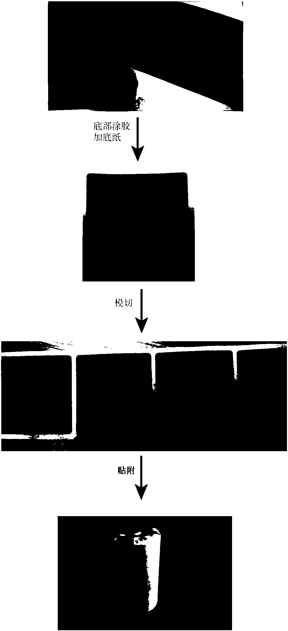
[0022] A battery packaging process, including the process of coating an insulating material on the outside of the battery cell, and the process of coating the insulating material on the outside of the battery cell includes the following steps: S1: Apply glue to the bottom surface of the kraft paper, and the material of the glue is Self-adhesive, and then add a base paper on the bottom surface of the kraft paper; S2: Die-cut the kraft paper into multiple rectangular paper pieces by using a die-cutting process, without cutting the base paper, and attach the multiple rectangular paper pieces to a piece of base paper Upper; S3: Use an automatic film sticking machine to attach each piece of kraft paper to each battery cell, the side of the kraft paper coated with glue is attached to the side of the battery cell, the kraft paper covers the entire side of the battery cell, and the At this time, the length of one side of each piece of kraft paper is parallel to the height direction of ...


PUM

PropertyMeasurementUnit
thicknessaaaaaaaaaa
heightaaaaaaaaaa
thicknessaaaaaaaaaa

Abstract

The invention discloses a battery packaging process, which includes the following steps: applying glue to the bottom surface of kraft paper, and then adding base paper to the bottom surface of kraft paper; using die-cutting technology to die-cut the kraft paper into multiple pieces; using an automatic film pasting machine to A piece of the kraft paper is attached to each battery core, and the glued side of the kraft paper is attached to the outer surface of the battery core; first, the kraft paper is made into self-adhesive kraft paper. Both kraft paper and self-adhesive kraft paper can be made. When stored in paper rolls, the sensitivity to air humidity is greatly reduced. The storage process is resistant to pressure, and there is no risk of pressure deformation. The space utilization rate is high; secondly, the film cutting process is used to die-cut the kraft paper into multiple pieces of paper. Compared with the traditional process, the production efficiency is increased by more than 30 times, and the material utilization rate is also increased by nearly 90%; thirdly, an automatic film laminating machine is used to attach each piece of kraft paper to the outer surface of the battery core, eliminating the need for kraft paper tube coating process The assembly fluctuation situation can produce more efficient and high-quality batteries.

Description

Technical field [0001] The present invention relates to the field of battery technology, and in particular to a battery packaging technology. Background technique [0002] In the process of assembling chemical power cells into battery packs, for battery packs that require high-rate charging and discharging, using plastic materials such as PVC or PET for insulation has problems with material shrinkage and aging. Therefore, kraft paper tubes are usually used to wrap the cells for insulation. Avoid shrinkage, aging and other problems of plastic materials. But first of all, due to the complex production process and low degree of automation of kraft paper tubes, the labor cost of kraft paper tube production is high, the material utilization is low, the finished product qualification rate is low, and the final kraft paper tube production cost is high. Secondly, after the kraft paper tube is formed, it needs to occupy A large amount of space leads to high storage and transportatio...

Claims


Application Information

Patent Timeline
Patent Type & Authority Patents(China)
IPC IPC(8): H01M2/02H01M10/04B32B37/00H01M50/107
CPCH01M10/04B32B37/00H01M50/107H01M50/10H01M50/116Y02E60/10Y02P70/50
Inventor 朱连山
Owner SHENZHEN HIGHPOWER TECH CO LTD
Learn More