
Metal wire grid polarizing film and liquid crystal display device

A technology of liquid crystal display devices and metal wire grids, applied in nonlinear optics, optics, optical components, etc., to achieve the effects of improving display quality, avoiding damage, and preventing color shift

Active Publication Date: 2016-10-12
TCL CHINA STAR OPTOELECTRONICS TECH CO LTD
View PDF5 Cites 30 Cited by
  • Summary
  • Abstract
  • Description
  • Claims
  • Application Information

AI Technical Summary

Problems solved by technology

[0008] The purpose of the present invention is also to provide a liquid crystal display device, by arranging blue light quantum dots in the metal wire grid polarizer, using the blue light emitted by the blue light quantum dots to compensate the problem of the low transmittance of the metal wire grid polarizer in the blue light region, Prevent color shift in liquid crystal display devices and improve display quality of liquid crystal display devices
[0009] The purpose of the present invention is also to provide a liquid crystal display device, by separately arranging the blue light quantum dot film layer in the liquid crystal display device, using the blue light emitted by the blue light quantum dots to compensate the problem of the low transmittance of the metal wire grid polarizer in the blue light region , to prevent color shift in liquid crystal display devices and improve the display quality of liquid crystal display devices

Method used


Image

  • Metal wire grid polarizing film and liquid crystal display device
  • Metal wire grid polarizing film and liquid crystal display device
  • Metal wire grid polarizing film and liquid crystal display device

Examples


Embodiment Construction

[0053] In order to further illustrate the technical means adopted by the present invention and its effects, the following describes in detail in conjunction with preferred embodiments of the present invention and accompanying drawings.

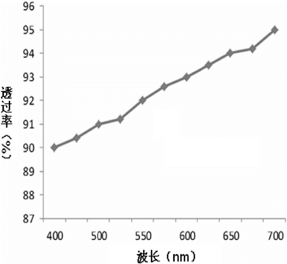
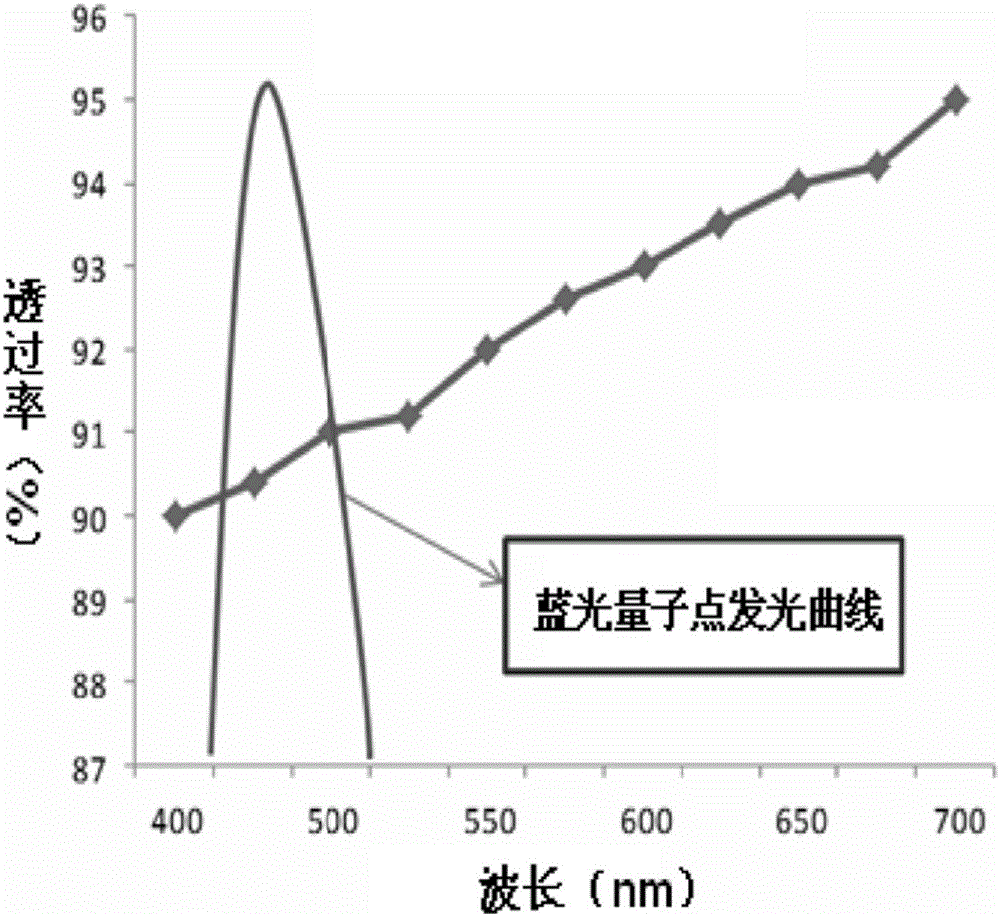
[0054] see figure 2 , is a schematic diagram of the light transmittance curve of the existing metal wire grid polarizer and the luminescence spectrum curve of the blue light quantum dots, from figure 2 It can be seen that the luminescence curve of the blue light quantum dots can roughly cover the blue light wavelength range where the transmittance of the metal wire grid polarizer is low. Therefore, based on this principle, the present invention uses blue light quantum dots to compensate for the metal wire grid polarizer In the problem of low transmittance in the blue light region, it prevents problems such as color shift in the liquid crystal display device.

[0055] see image 3 , the present invention provides a metal wire grid polarizer...


PUM

PropertyMeasurementUnit
widthaaaaaaaaaa
thicknessaaaaaaaaaa
thicknessaaaaaaaaaa

Abstract

The invention provides a metal wire grid polarizing film and a liquid crystal display device. The metal wire grid polarizing film comprises blue light quantum dots, the blue light emitted by blue light quantum dots is used to compensate the problem of the low transmission rate of the metal wire grid polarizing film in a blue light area, the color cast of the liquid crystal display device is prevented, and the display quality of the liquid crystal display device is improved. According to the liquid crystal display device of the invention, through arranging the blue light quantum dots in the metal wire grid polarizing film or individually arranging a blue light quantum dot film layer in the liquid crystal display device, the blue light quantum dots can absorb the UV light and blue violet light of the short wave high energy emitted by a blue light emitting diode, the light utilization rate of a back light source can be improved, the damage to eyes by the UV light and blue violet light with short wavelengths can be avoided, at the same time, the blue light emitted by the blue light quantum dots can compensate the problem of the low transmission rate of the metal wire grid polarizing film in the blue light area, the color cast of the liquid crystal display device is prevented, and the display quality of the liquid crystal display device is improved.

Description

technical field [0001] The invention relates to the field of display technology, in particular to a metal wire grid polarizer and a liquid crystal display device. Background technique [0002] With the development of science and technology and the progress of society, people are increasingly dependent on information exchange and delivery. As the main carrier and material basis of information exchange and transmission, display devices, especially Liquid Crystal Display (LCD), have become the focus of more and more people's attention, and are widely used in all aspects of work and life. [0003] For a liquid crystal display device, a backlight source is an essential part thereof. Generally speaking, the backlight of a liquid crystal display device uses blue light emitted by a blue light-emitting diode (LED, Light Emitting Diode) to excite yttrium aluminum garnet (YAG) phosphors, which form white light after modulation. The blue light emitted by ordinary blue light-emitting d...

Claims


Application Information

Patent Timeline
Patent Type & Authority Applications(China)
IPC IPC(8): G02B5/30G02F1/1335G02F1/13357
CPCG02B5/3058G02F1/133528G02F1/133617G02F1/133548
Inventor 陈黎暄李明辉李冬泽
Owner TCL CHINA STAR OPTOELECTRONICS TECH CO LTD
Learn More