


Quick Research
Generate reliable direction feasibility study reports for your R&D in just a few steps.

Technical Q&A
Discover and master advanced knowledge NOW. Basics, ideas, possibilities, all at once.

Find Solutions
As an expert in R&D theories, this can generate solutions to your technical problems instantly.

Evaluate Feasibility
Analyze your overall solution with one click, know your potential R&D risks in advance.

Monitor Landscape
Get weekly tech updates, stay abreast of the latest tech innovations and key insights.
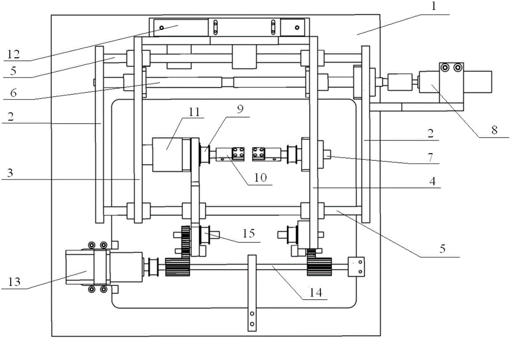
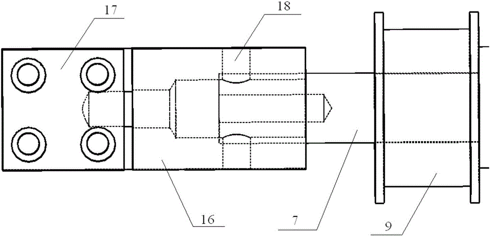
In-situ test device for three-dimensional defect reconstruction
An in-situ test and defect technology, applied in the direction of measuring devices, using applied repetitive force/pulsation force to test material strength, using applied stable tension/pressure to test material strength, etc., can solve the problems that cannot be realized
- Summary
- Abstract
- Description
- Claims
- Application Information
AI Technical Summary
Problems solved by technology
Method used
Image


Examples
Embodiment Construction
[0017] Below in conjunction with accompanying drawing, the present invention will be further described:
[0018] Such as Figure 1 to Figure 4 As shown, the in-situ test device for three-dimensional defect reconstruction includes a hollow frame structure 1 and a transmission mechanism. The frame structure 1 adopts a hollow structure to facilitate the passage of X-rays. The left and right sides of the frame structure 1 are respectively symmetrically provided with baffles 2, and the left beam 3 and the right beam 4 are slidably connected between the baffles 2 through the guide rail 5, and the left beam 3 and the right beam are also provided between the baffles 2. The rotating lead screw 6 connected with the beam 4, the two ends of the rotating lead screw 6 are provided with reverse threads, one side of the frame structure 1 is provided with a pulling motor 8 connected with the rotating lead screw 6, and the stretching motor 8 drives the two The rotating screw rod 6 with reverse...
PUM
 Abstract
Description
Claims
Application Information
 - R&D Engineer
- R&D Manager
- IP Professional
- Industry Leading Data Capabilities
- Powerful AI technology
- Patent DNA Extraction
Browse by: Latest US Patents, China's latest patents, Technical Efficacy Thesaurus, Application Domain, Technology Topic, Popular Technical Reports.
© 2024 PatSnap. All rights reserved.Legal|Privacy policy|Modern Slavery Act Transparency Statement|Sitemap|About US| Contact US: help@patsnap.com