Insulation pipe type busbar three-layer coextrusion continuous vulcanization production equipment and production process

A three-layer co-extrusion and production equipment technology, which is applied in the direction of conductor/cable insulation, electrical components, circuits, etc., can solve the problem of no insulating tubular busbar production equipment and production process, short length of single conductor tube, conductor tube load Large flow and other problems, to reduce production costs and labor intensity of workers, achieve diversity, improve the effect of insulation strength

Inactive Publication Date: 2016-10-12
周龙刚
View PDF0 Cites 1 Cited by
  • Summary
  • Abstract
  • Description
  • Claims
  • Application Information

AI Technical Summary

Problems solved by technology

[0002] Insulated tubular busbars are widely used in the field of power transmission because of their large carrying capacity and low skin effect. However, the conductor tube is a hard conductor, and the short length of a single conductor tube restricts its The bottleneck of the development of insulation technology; after searching the existing technology, it is found that there is no production equipment and production process for the production of insulating tubular busbars by continuous extrusion and continuous vulcanization. In order to improve the withstand voltage level of insulating tubular busbars and improve the product performance, there is an urgent need to develop a three-layer co-extrusion continuous vulcanization production equipment and production process for insulating tubular busbars, to achieve the process requirements for continuous extrusion and continuous vulcanization of insulating tubular busbars, and to improve product quality and production capacity

Method used


Image

  • Insulation pipe type busbar three-layer coextrusion continuous vulcanization production equipment and production process
  • Insulation pipe type busbar three-layer coextrusion continuous vulcanization production equipment and production process

Examples


Embodiment Construction

[0031] This embodiment is carried out on the premise of the technical solutions of the above inventions, and detailed implementation methods and specific operation processes are given, but the scope of protection of the present invention is not limited to the following embodiments.

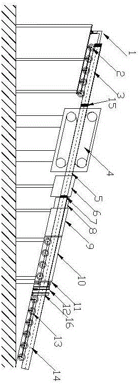
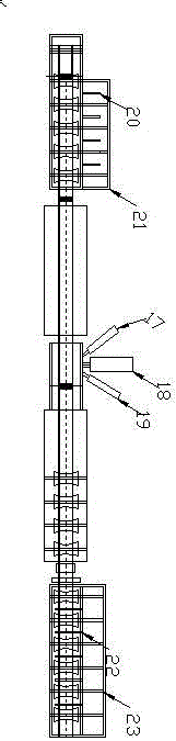
[0032] Such as figure 1 As shown, a three-layer co-extrusion continuous vulcanization production equipment for pipe bus includes: conductor pipe connection auxiliary push car 1, conductor pipe connection platform 2, conductor pipe 3, pneumatic crawler pusher 4, conductor pipe 5, three-layer co-extrusion Machine head 6, conductor pipe connection pin 7, upper sealer 8, vulcanization pipe 9, cooling pipe 10, lower sealer 11, pneumatic pressing device 12, stripping and cutting platform 13, extrusion pipe busbar 14, conductor pipe connection pin 15. Stripping and cutting machine 16, first extruder 17, second extruder 18, third extruder 19, manipulator 20, conductor tube placement platform 21, manipulat...


PUM


Abstract

The invention discloses insulation pipe type busbar three-layer coextrusion continuous vulcanization production equipment and a production process. The equipment comprises a conductor pipe connecting auxiliary pushing car, a conductor pipe connecting platform, conductor pipe connecting pins, an air-pressure track pusher, a three-layer coextrusion machine head, an upper closer, a vulcanization pipe, a cooler, a lower closer, an air-pressure pressing device, an insulation stripping cutter and a stripping cutting platform positioned on the same inclined surface from high to low in sequence. The production process comprises the following steps: single conductor pipes are connected continuously by the connecting pins to satisfy the continuous extrusion and continuous vulcanization technical requirements; a production line is aslant arranged to eliminate the gravity dropping influence of the conductor pipes for free insulation vulcanization; the pressing device is used for eliminating aslant downward sliding force of the conductor pipes and improving the extrusion stability; and the scheme satisfies the continuous extrusion and continuous vulcanization production requirements of high-voltage-grade insulation pipe type busbars.

Description

technical field [0001] The invention relates to a three-layer co-extrusion continuous vulcanization production equipment and a production process of an insulating tubular busbar. Background technique [0002] Insulated tubular busbars are widely used in the field of power transmission because of their large carrying capacity and low skin effect. However, the conductor tube is a hard conductor, and the short length of a single conductor tube restricts its The bottleneck of the development of insulation technology; after searching the existing technology, it is found that there is no production equipment and production process for the production of insulating tubular busbars by continuous extrusion and continuous vulcanization. In order to improve the withstand voltage level of insulating tubular busbars and improve the product performance, there is an urgent need to develop a three-layer co-extrusion continuous vulcanization production equipment and production process for ins...

Claims


Application Information

Patent Timeline
Patent Type & Authority Applications(China)
IPC IPC(8): B29C47/08B29C35/00H01B13/00H01B13/14
CPCB29C35/00B29C48/025H01B13/00H01B13/141
Inventor 周龙刚
Owner 周龙刚
Why Eureka
Try Eureka