
Pulley type stacking mechanical arm

A technology of mechanical arms and pulleys, which is applied in the field of palletizing machinery, can solve the problems of low energy utilization efficiency of mechanical arms, and achieve the effect of small output torque and improved energy utilization efficiency

Active Publication Date: 2016-10-12
沈阳实发汽车配件有限公司
View PDF7 Cites 2 Cited by
  • Summary
  • Abstract
  • Description
  • Claims
  • Application Information

AI Technical Summary

Problems solved by technology

[0003] The above robotic arms have a common problem. Even when the robotic arm is empty, as long as the robotic arm moves, it still needs to consume a lot of energy for the movement of the robotic arm itself. Therefore, the smaller the mass of the cargo carried by the robotic arm, the more The less efficient the use of energy

Method used


Image

  • Pulley type stacking mechanical arm
  • Pulley type stacking mechanical arm

Examples


Embodiment Construction

[0014] In order to make the technical means, creative features, goals and effects achieved by the present invention easy to understand, the present invention will be further described below in conjunction with specific embodiments.

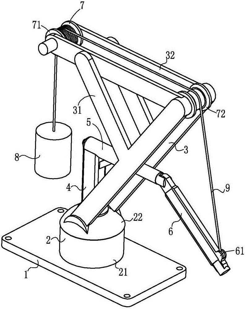
[0015] Such as figure 1 , figure 2 , a pulley-type palletizing robot arm in this embodiment includes a base plate 1, a base 2, a bracket 3, a support column 4, a hydraulic arm 5, a movable arm 6, a pulley 7, a balance weight 8 and a traction line 9.

[0016] The base 2 is cylindrical, and the base 2 includes a fixed seat 21 arranged on the substrate 1 and a rotating seat 22 arranged above the fixed seat 21; the support 3 is fixed on the rotating seat 22, and the middle part of the support 3 is arranged There is a branch bar 31, and the top of the bracket 3 is provided with a cross bar 32; the support column 4 is vertically fixed on the swivel seat 22; one end of the hydraulic arm 5 is fixedly connected to the top of the support column 4, and the...


PUM


Abstract

The invention relates to the field of stacking machines, in particular to a pulley type stacking mechanical arm. The pulley type stacking mechanical arm comprises a base plate, a base, a support, a supporting column, a hydraulic arm, a movable arm, a pulley, a balance block and a pull rope. The base comprises a fixed base body arranged on the base plate and a rotary base body arranged on the fixed base body. The support is fixed to the base. The supporting column is vertically fixed to the rotary base body. The two ends of the hydraulic arm are hinged to the supporting column and the movable arm correspondingly. The pulley comprises an active rolling wheel and a fixed pulley body, the active rolling wheel and the fixed pulley body are arranged on the support, and the side face of the active rolling wheel is connected with a motor. One end of the pull rope is fixed to the other end of the movable arm, the middle portion of the pull rope winds across the fixed pulley body, and the other end of the pull rope is wound on the active rolling wheel by a plurality of circles. The balance block is connected with the other end of the pull rope and arranged in a suspended mode. According to the pulley type stacking mechanical arm, the rope and the pulley are used for force transmission, and the stress difference between the two ends of the rope is made smaller so that the output torque of the driving motor can be smaller when the mechanical arm moves, and the mechanical arm can save more energy.

Description

technical field [0001] The invention relates to the field of palletizing machinery, in particular to a pulley type palletizing mechanical arm. Background technique [0002] At present, in the field of industrial automation production, various special machines or mechanical arms are used to carry and stack materials to improve operating efficiency and overall productivity. According to the different conditions of the production line and the volume and weight of the material, these devices have different shapes. Compared with special-purpose machines, robotic arms have been widely used in the field of material handling and stacking due to their small footprint, simple structure, flexible operation, and flexible operations. The structural forms of the manipulator are more representative, such as the general-purpose articulated industrial manipulator, or the SCARA-shaped plane coordinate manipulator, etc. [0003] The above robotic arms have a common problem. Even when the rob...

Claims


Application Information

Patent Timeline
Patent Type & Authority Applications(China)
IPC IPC(8): B25J9/12B65G61/00
CPCB25J9/12B65G61/00
Inventor 刘长苗
Owner 沈阳实发汽车配件有限公司
Learn More