Falling film melt polycondensation reaction method and reactor between rows of tubes
A technology of melt polycondensation and reactor, which is applied in the field of falling film melt polycondensation reaction between rows of tubes and its reactor, which can solve the problems of slow inner layer film, affecting product quality, degradation, etc.
- Summary
- Abstract
- Description
- Claims
- Application Information
AI Technical Summary
Problems solved by technology
Method used
Image
Examples
Embodiment 1
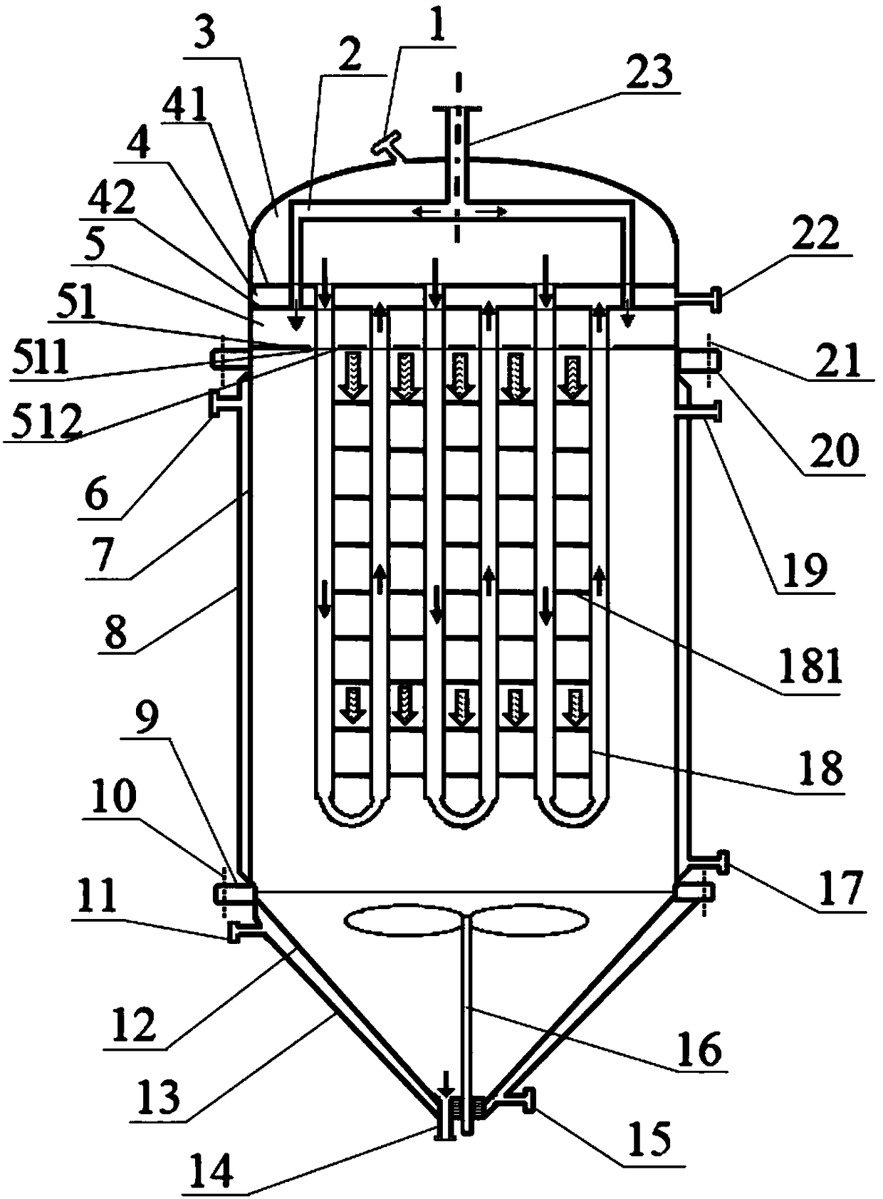
[0027] Embodiment 1, with reference to attached figure 1 , 4 , 5a, 5b, 5c.
[0028] In this embodiment, the straight tubes of U-shaped heat exchange tubes 18 (hereinafter referred to as U-shaped tubes, which include straight tubes on both sides and bent tubes connecting the straight tubes on both sides at the bottom end) adopt straight tubes with constant diameters. .
[0029] A kind of fall-film melt polycondensation reactor between rows of tubes provided by the present embodiment, such as figure 1As shown, it includes a vertical housing 7, a material feed box connected to the upper end of the vertical housing 7 and a bottom shell 12 at the lower end, a heat medium outflow box 4 is arranged above the material feed box 5, and the heat medium flows out A heat medium inflow box 3 is provided on the box 4, a reactor heat medium inlet 1 is arranged on the heat medium inflow box 3, and a reactor heat medium outlet 22 is arranged on the heat medium outflow box 4, arranged in rows...
Embodiment 2
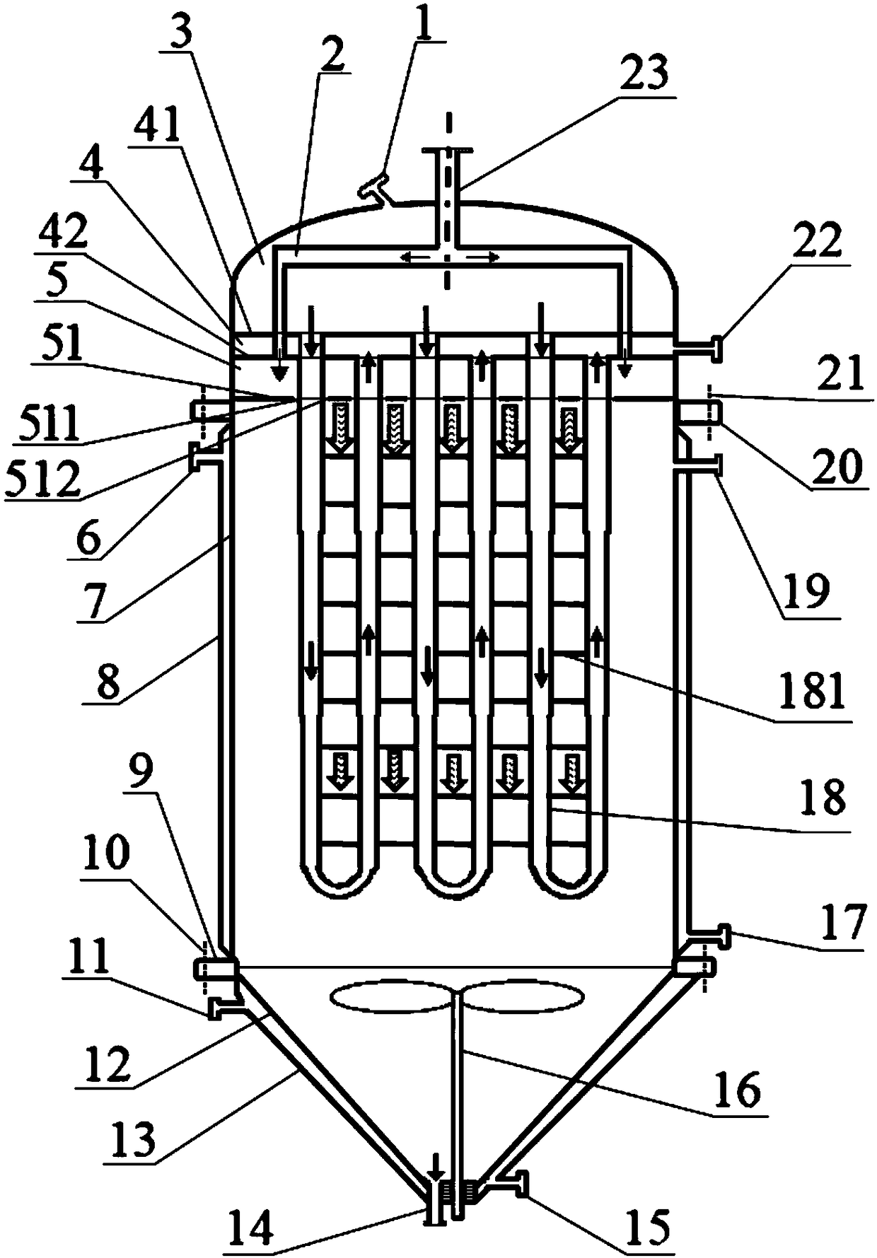
[0048] Embodiment 2, with reference to attached figure 2 , 4 , 5a, 5b, 5c.
[0049] In this embodiment, the straight tube of the U-shaped tube 18 adopts a connected coaxial straight tube with reduced diameter.
[0050] The straight pipe of the U-shaped pipe 18 is reduced in diameter at the same distance below the cloth plate 51 to become a straight pipe with different diameters but continuous communication, coaxial up and down, from the bottom of the cloth plate 51 to the bottom of the U-shaped pipe 18, the pipe diameter slowing shrieking.
[0051] On the reduced-diameter U-shaped pipe, the length of the connecting wire between the straight pipes of each U-shaped pipe is kept equal to the distance between the pipes of the corresponding reduced-diameter straight pipes.
[0052] Other parts and implementation method of this embodiment are the same as embodiment 1, in figure 2 , the reference numerals and figure 1 The same means the same meaning.
Embodiment example 3
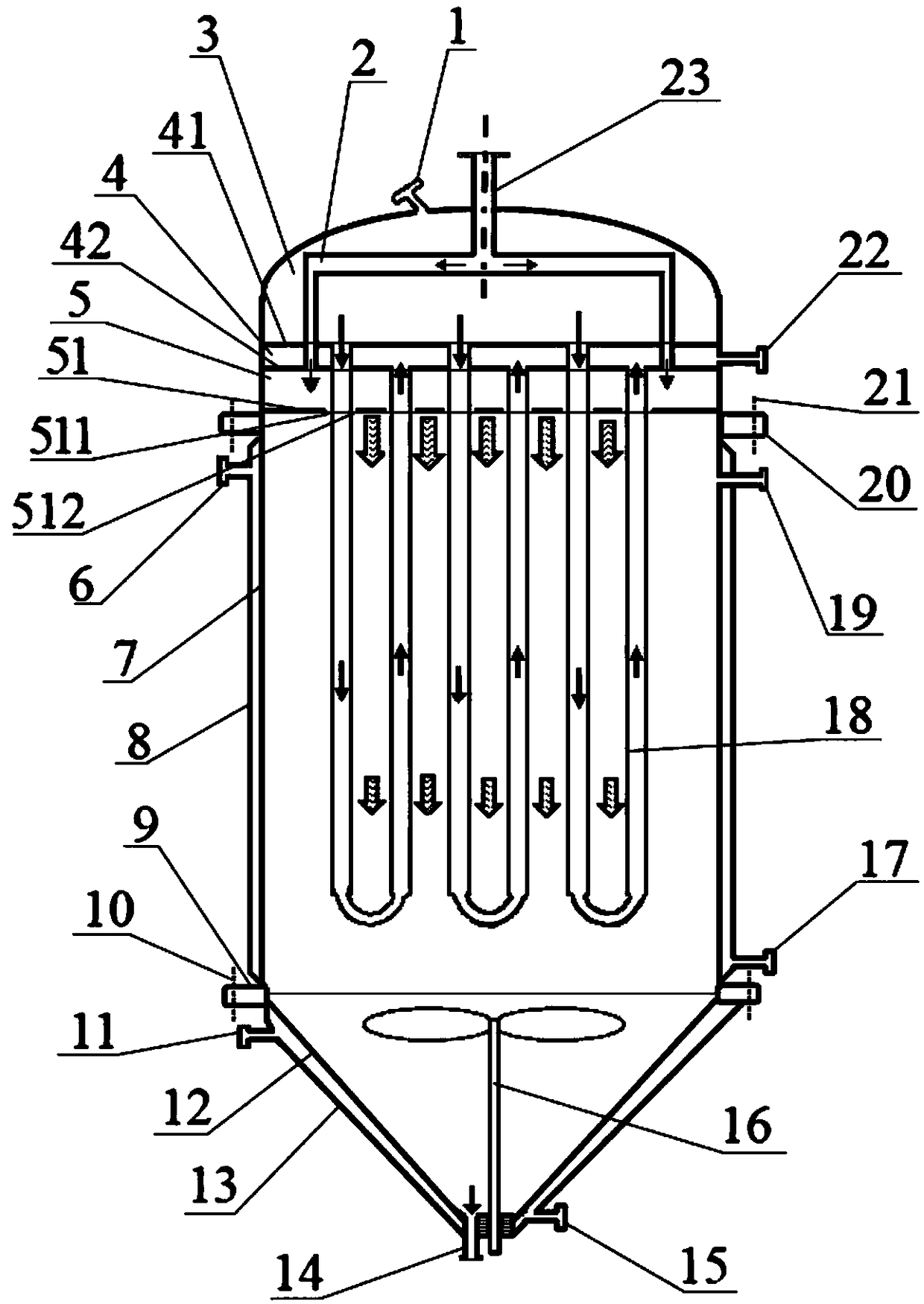
[0053] Implementation case 3, refer to the attached image 3 , 4 , 5a, 5b, 5c.
[0054] In this embodiment, the straight part of the U-shaped tube 18 is a straight tube with a constant diameter, and there is no connecting wire between two straight tubes of the U-shaped tube 18 and between two adjacent straight tubes of the adjacent U-shaped tubes 18 in the same row.
[0055] Preferably, the ratio of the distance between the U-shaped tubes 18 to the tube diameter is 0.1-10.
[0056] Other parts and implementation method of this embodiment are the same as embodiment 1, in image 3 , the reference numerals and figure 1 The same means the same meaning.
PUM
 Abstract
Description
Claims
Application Information
 - R&D
- Intellectual Property
- Life Sciences
- Materials
- Tech Scout
- Unparalleled Data Quality
- Higher Quality Content
- 60% Fewer Hallucinations
Browse by: Latest US Patents, China's latest patents, Technical Efficacy Thesaurus, Application Domain, Technology Topic, Popular Technical Reports.
© 2025 PatSnap. All rights reserved.Legal|Privacy policy|Modern Slavery Act Transparency Statement|Sitemap|About US| Contact US: help@patsnap.com


