Eureka AIR delivers breakthrough ideas for toughest innovation challenges, trusted by R&D personnel around the world.

Bottom plate jacking system for jacking closure section of continuous rigid frame bridge and construction method of bottom plate jacking system

A technology for rigid frame bridges and closing sections, applied in bridges, bridge construction, erection/assembly of bridges, etc., can solve the problems of lower overall rigidity of the outer rigid support structure, low reuse rate, troublesome construction, etc., to achieve processing and installation The effect of simple layout, low construction cost and flexible use

Inactive Publication Date: 2016-09-28
XIAN HIGHWAY INST
View PDF9 Cites 0 Cited by
  • Summary
  • Abstract
  • Description
  • Claims
  • Application Information

AI Technical Summary

Problems solved by technology

[0010] At present, when designing the bottom plate push base, due to the small thickness of the bottom plate in the closing section, generally about 25cm to 35cm, there is a problem of insufficient depth for directly embedding steel plate bolts and other fasteners, so the thickness needs to be increased locally
The existing technical solution is to pre-embed a steel plate on the top of the pre-added concrete block as the base for pushing the bottom plate, but this technical solution has the following defects: first, the structure and force transmission mechanism are complicated, and the longitudinal thrust of the rigid support structure is first transmitted to the The pre-embedded steel plate is then transferred to the concrete block through the pre-embedded steel plate, and finally transferred to the bottom slab concrete of the closing section; second, the position of the pushing point is high and the additional bending moment is large
[0011] Nowadays, when pushing the closing section of a continuous rigid frame bridge, usually no special reaction frame is set up, but the embedded steel bracket is used as the base to take into account the reaction frame, and there are also rigid struts directly connected to the embedded base ( That is, the method of the outer rigid support structure), cutting off the part that affects the concrete of the bridge deck pavement after the jacking is completed, but the above-mentioned existing construction schemes all have the following defects: first, the locking and pushing positions are located in the outer rigid support structure The middle part of the outer rigid support structure is complex due to the need to set a jack, and the overall rigidity of the outer rigid support structure is reduced; second, the locking is performed by on-site welding, which is troublesome in construction, and the error is not easy to adjust after welding and locking; third, After the jacking and concrete pouring are completed, it needs to be cut and dismantled, and the reuse rate is low; Fourth, the center of gravity of the component is high, and the additional bending moment is large during the jacking
But at present, there is a lack of a counter force frame capable of oblique thrusting, and it is impossible to perform oblique thrusting

Method used


Image

  • Bottom plate jacking system for jacking closure section of continuous rigid frame bridge and construction method of bottom plate jacking system
  • Bottom plate jacking system for jacking closure section of continuous rigid frame bridge and construction method of bottom plate jacking system
  • Bottom plate jacking system for jacking closure section of continuous rigid frame bridge and construction method of bottom plate jacking system

Examples


Embodiment 2

[0178] Such as Image 6 As shown, in this embodiment, the difference from embodiment 1 is that the rigid support is a second support, and the second support is composed of two symmetrically arranged support angles 5-2-2, two The supporting angle steel 5-2-2 is welded and fixed to the lower supporting steel plate 5-1.

[0179] In this embodiment, the structure and connection relationship of the remaining parts of the bottom plate pushing system used are the same as those in the first embodiment.

[0180] In this embodiment, the construction method of the bottom plate pushing system adopted is the same as that of the first embodiment.

Embodiment 3

[0182] Such as Figure 7 As shown, in this embodiment, the difference from embodiment 1 is that the rigid support is a third support, and the third support is supported by two symmetrically arranged vertical steel plates 5-2-3 and It is composed of upper supporting steel plates 5-2-4 on the two vertical steel plates 5-2-3. In addition, the two vertical steel plates 5-2-3 are both welded and fixed on the lower support steel plate 5-1. The upper support steel plate 5-2-4 is a rectangular steel plate and its size is the same as the size of the lower support steel plate 5-1. The upper support steel plate 5-2-4 and the two vertical steel plates 5-2-3 They are all fixedly connected by welding.

[0183] In this embodiment, the structure and connection relationship of the remaining parts of the bottom plate pushing system used are the same as those in the first embodiment.

[0184] In this embodiment, the construction method of the bottom plate pushing system adopted is the same as that ...


PUM


Abstract

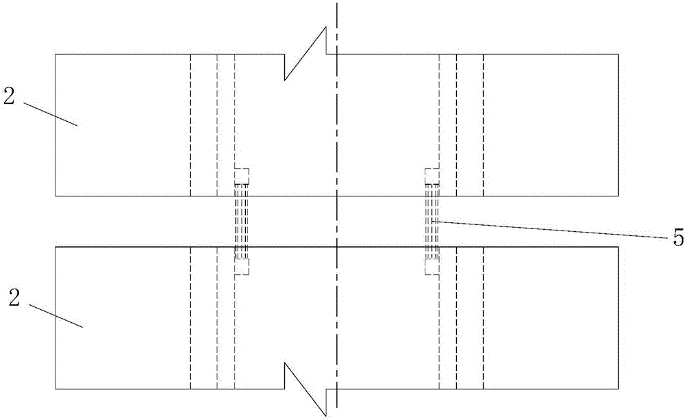
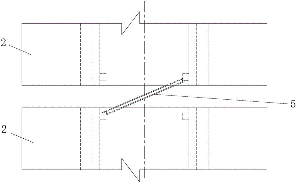
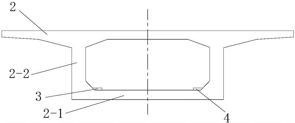
The invention discloses a bottom plate jacking system for jacking a closure section of a continuous rigid frame bridge and a construction method of the bottom plate jacking system. The bottom plate jacking system comprises two sets of bottom plate embedded bases arranged at the ends of two cantilever beam sections of the continuous rigid frame bridge correspondingly, rigid supporting structures supported between the two sets of bottom plate embedded bases and a jacking mechanism used for jacking the rigid supporting structures. Each set of bottom plate embedded bases comprises a left bottom plate embedded base and a right bottom plate embedded base distributed on the same cantilever beam section. The rigid supporting structures are supporting structures for longitudinal jacking or supporting structures for oblique jacking. One ends of the rigid supporting structures are the fixing ends, and the other ends of the rigid supporting structures are jacking ends. The construction method comprises the steps of (1) construction of the bottom plate embedded bases, (2) mounting of the jacking mechanism and (3) mounting of the rigid supporting structures. The bottom plate jacking system is reasonable in design, easy and convenient to construct and good in use effect, the jacking process of the cantilever beam sections on the two sides of the closure section can be completed easily, conveniently and rapidly, and the correction requirements of lateral deviation and reverse deviation of the cantilever beam sections can be met.

Description

Technical field [0001] The invention belongs to the technical field of bridge construction, and in particular relates to a bottom plate pushing system for pushing the closed section of a continuous rigid frame bridge and a construction method thereof. Background technique [0002] Continuous rigid frame bridges are continuous beam bridges with piers and beams consolidated. Multi-span rigid-frame bridges with continuous beams and multi-span continuous-rigid-frame bridges all use prestressed concrete structures with more than two main piers. The pier-beam consolidation system has the advantages of a T-shaped rigid frame bridge and a continuous beam bridge. The closing section is a key link in the construction of continuous rigid frame bridges. In order to reduce the adverse effects of concrete shrinkage, creep and temperature changes on the bridge structure during the operation period, jack jacks are generally used during the construction of the closing section of the continuous ri...

Claims


Application Information

Patent Timeline
IPC IPC(8): E01D21/06E01D21/10
CPCE01D21/06E01D21/10
Inventor 王卫山刘永健袁卓亚蒲广宁王旭朱伟庆舒涛马印平贾德生郭亮
Owner XIAN HIGHWAY INST
Why Eureka
Eureka Blog
Learn More