Eureka AIR delivers breakthrough ideas for toughest innovation challenges, trusted by R&D personnel around the world.

Punching production main machine

A main engine and punching technology, applied in the direction of piercing tools, metal processing equipment, manufacturing tools, etc., can solve the problems of low production efficiency, low safety factor, high work intensity, etc.

Active Publication Date: 2016-09-28
济南天辰智能装备股份有限公司
View PDF9 Cites 5 Cited by
  • Summary
  • Abstract
  • Description
  • Claims
  • Application Information

AI Technical Summary

Problems solved by technology

At present, the processing equipment in the domestic steel structure industry is mainly based on the drilling production line, and the processing method is drilling. The main problem is that the processing efficiency is low; the processing equipment in the domestic aluminum formwork industry is mainly based on a single punching machine. The processing method is a single-machine punching method. After manually picking up the profile, punch the holes on one side of the wing on the punching machine, turn the workpiece over after completion, and then punch the holes on the other side, which has low safety factor and work. Disadvantages such as high strength, high labor cost, and low production efficiency; when there are different hole spacings on the workpiece, the punches that do not need to be punched can only be removed to ensure the hole spacing, especially when there are many different holes on the workpiece. The processing efficiency is lower or even impossible when the hole spacing is used. The punching production host of the present invention can be applied in the production line, and can realize the processing of any hole spacing with the assistance of the feeding device.

Method used


Image

  • Punching production main machine
  • Punching production main machine
  • Punching production main machine

Examples


Embodiment 1

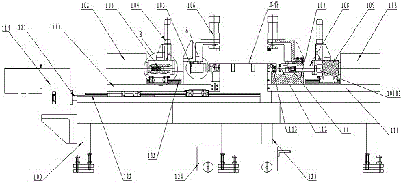
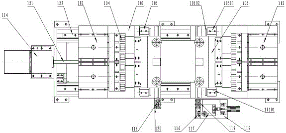
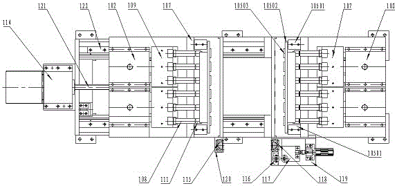
[0082] Such as Figure 1 to Figure 3 As shown, a punching production host includes a base, a punching device, a hydraulic power device and an electrical control device. The base is provided with a fixed base 110, a mobile base 101 and a driving device for the mobile base. The punching device includes a left punching device and a right punching device, the left punching device is arranged on the mobile base 101 , and the right punching device is arranged on the fixed base 110 .

[0083] The base 100 is provided with two first guide rails 122, and the mobile base driving device drives the mobile base 101 to move along the first guide rails 122 in the Y direction;

[0084] Mobile base drives include:

[0085] The servo power device 114 is fixed on the base 100,

[0086] Lead screw 121, one end links to each other with servo power unit 114, present embodiment adopts ball screw,

[0087] The screw nut is connected to the lower part of the mobile base 101 and meshes with the bal...

Embodiment 2

[0119] A punching production host, the upper pressing device 106 includes a cylinder bracket 10601, an upper pressing cylinder 10602, a guide post 10603, a guide sleeve 10604, a linear bearing, an upper pressing plate 10606, and an upper pressing block 10607; The lower end of the left side of the support 10601 is connected to the top of the left vertical plate of the formwork 107 with bolts, and the upper side pressing cylinder 10602 is vertically installed on the upper end of the right side of the cylinder support 10601, and the piston rod of the upper side pressing cylinder 10602 is connected with the upper side. The binder plate 10607 is fixed with bolts, and the guide sleeve 10604 is fixed on the cylinder bracket 10601 with bolts. The inner side of the guide sleeve 10604 is equipped with a linear bearing, and the guide post 10603 can slide along the linear bearing. The lower end of the guide post 10603 and the upper binder plate 10606 is connected with bolts, and the upper ...

Embodiment 3

[0122] A punching production host, the upper pressing device 106 includes a cylinder bracket 10601, a multi-axis cylinder, an upper pressing plate 10606, and an upper pressing block 10607; the lower end of the left side of the cylinder bracket 10601 is connected to the mold frame 107 by bolts On the upper part of the left vertical plate, the multi-axis cylinder is vertically installed on the upper end of the right side of the cylinder bracket 10601. The piston rod of the multi-axis cylinder is connected with the upper pressing plate 10607 with bolts, and the upper pressing block 10607 is connected with the upper pressing plate with bolts. The bottom surface of the material plate 10606; the rest of the structure is the same as that of the first embodiment.


PUM


Abstract

The invention discloses a punching production main machine. The punching production main machine comprises a base, a fixed machine base, a movable machine base, die changing devices, pressing devices, a positioning device, a floating supporting device, a servo power device, a hydraulic power device and an electrical control device. The fixed machine base is fixed to the base, and the movable machine base can move in the Y direction along a guide rail on the base. The servo power device is fixed to the base. The punching production main machine is characterized in that each of the fixed machine base and the movable machine base is provided with a hydraulic power cylinder, a pressing head and a die frame; each pressing head is provided with the corresponding die changing device and internally provided with a resilience device; and each die frame is provided with the corresponding upper side pressing device, the corresponding side face pressing device, a punch rod, a punch nut, a punch and a female die. According to the technical scheme, operation is convenient, the automation degree is high, and the machining precision is improved; and the work hour is reduced, the machining cost is reduced, and the production efficiency is improved.

Description

technical field [0001] The invention relates to the technical field of profile processing equipment, in particular to a punching processing host for profiles such as profile steel and aluminum templates. Background technique [0002] Various types of steel structure buildings composed of various section steels use a large number of section steels connected by bolts. In order to realize the bolt connection between various section steels, various holes need to be processed on the section steels. As a new type of building material, aluminum formwork is also widely used in the construction industry due to its environmental protection, greenness, low cost of use, and recyclability. When used, aluminum formwork also needs to be connected by bolts or pins. Therefore, aluminum formwork also needs to be connected every 50 or Integer multiples of 50 mm punch a connection hole. At present, the processing equipment in the domestic steel structure industry is mainly based on the drillin...

Claims


Application Information

Patent Timeline
IPC IPC(8): B21D28/24B21D28/34
CPCB21D28/243B21D28/34
Inventor 李志刚陈晓萍吕多勇路光华
Owner 济南天辰智能装备股份有限公司
Why Eureka
Eureka Blog
Learn More