Microwave plasma torch ionization source and ionization mass spectrometry analysis method
A technology of microwave plasma and microwave plasma, which is applied in the direction of ion source/gun, material analysis and material analysis through electromagnetic means, can solve the problems of long sample channel, large volume, slow analysis speed, etc., and achieve sample consumption The effect of less, lower analysis cost, and faster analysis speed
- Summary
- Abstract
- Description
- Claims
- Application Information
AI Technical Summary
Problems solved by technology
Method used
Image
Examples
Embodiment 1
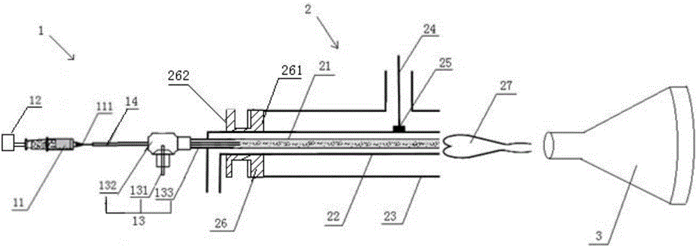
[0044] exist figure 1 In the shown embodiment one, the microwave plasma torch ionization source of the present invention includes a sample introduction system and a microwave plasma torch 2 placed horizontally and coaxially sequentially from left to right, and the head of the microwave plasma torch 2 is provided with The open end faces the mass spectrometer scanner 3 , and the sample injection system is coupled to the tail of the microwave plasma torch 2 . The sample introduction system of the present invention adopts the spray sample introduction device 1 to replace the desolvation device of the traditional microwave plasma torch ionization source, to simplify the sample introduction system, wherein:
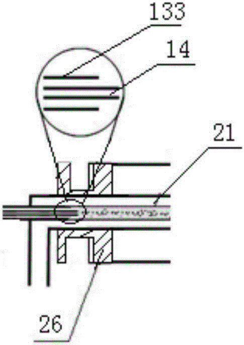
[0045] The spray sampling device 1 includes a sample injector, a carrier gas tube 13 and a sample nozzle 14, the carrier gas tube 13 includes a carrier gas inlet tube 131, a carrier gas tube sleeve 132 and a carrier gas tube body 133, and the carrier gas tube sleeve 132 is set ...
Embodiment 2
[0054] exist image 3 In the second embodiment shown, the injector structure of the spray sampling device 1 is different from that of the first embodiment, and other components are the same. In the second embodiment, the micro-sampler 11 and the sampling pump 12 in the sampler of the spray sampling device 1 are replaced by the carrier gas input pipe 11' and the Erlenmeyer flask 12', and the sample is filled into the Erlenmeyer flask 12' Among them, one end of the carrier gas input pipe 11' is connected to the carrier gas source, and one end is inserted into the sample of the Erlenmeyer flask 12', and the upper part of the Erlenmeyer flask 12' is communicated with the sample nozzle 14; the sample can be an aerosol, or an aerosol and The mixture flow of plasma gas, of course, can also be other material flow used for spectroscopic analysis, and the sample is carried by the carrier gas passed into the Erlenmeyer flask 12 ′ to the inner tube 21 of the microwave plasma torch 2 . Th...
Embodiment 3
[0071] Figure 10 In the shown embodiment three, a Nafion drying tube 4 (existing molded product) is connected in series between the spray sampling device 1 and the microwave plasma torch 2, and other components are the same as those in the first or second embodiment. In Embodiment 3, the Nafion drying tube 4 is placed coaxially with the sample nozzle 14 and the microwave plasma torch 2, including a Nafion membrane tube 41, a casing 42 sleeved outside the Nafion membrane tube, and a purge gas inlet 43 And purge gas outlet 44, the inlet of Nafion film tube 41 is connected with the carrier gas tube body 133 of carrier gas tube 13, the outlet of Nafion film tube 41 is connected with the inner tube 21 of microwave plasma torch tube 2, and the dry purge gas (such as nitrogen or air) is continuously blown in from the purge gas inlet 43, because there is a humidity difference inside and outside the Nafion membrane tube 41, the moisture content of the moist oxygen in the Nafion membra...
PUM
 Abstract
Description
Claims
Application Information
 - Generate Ideas
- Intellectual Property
- Life Sciences
- Materials
- Tech Scout
- Unparalleled Data Quality
- Higher Quality Content
- 60% Fewer Hallucinations
Browse by: Latest US Patents, China's latest patents, Technical Efficacy Thesaurus, Application Domain, Technology Topic, Popular Technical Reports.
© 2025 PatSnap. All rights reserved.Legal|Privacy policy|Modern Slavery Act Transparency Statement|Sitemap|About US| Contact US: help@patsnap.com


