Smart antenna self-adaptive control algorithm of fixed dwell time

An adaptive control, dwell time technology, applied in computing, electromagnetic radiation induction, induction record carrier, etc., can solve the problem of no beam switching adaptive control algorithm and so on

Inactive Publication Date: 2016-09-21
TIANJIN POLYTECHNIC UNIV
View PDF4 Cites 0 Cited by
  • Summary
  • Abstract
  • Description
  • Claims
  • Application Information

AI Technical Summary

Problems solved by technology

The beam switching type array antenna increases the gain of the antenna, and the beam is narrowed, but because the beam scans in multiple directions, the total identification area is expanded, such as figure 1 As shown, the sum of the coverage areas of beams 1, 2, 3, and 4 is larger than that of a single low-gain fixed beam
[0006] Existing research mainly focuses on the anti-collision algorithm of tags, but there is no corresponding beam switching adaptive control algorithm

Method used


Image

  • Smart antenna self-adaptive control algorithm of fixed dwell time
  • Smart antenna self-adaptive control algorithm of fixed dwell time
  • Smart antenna self-adaptive control algorithm of fixed dwell time

Examples


Embodiment Construction

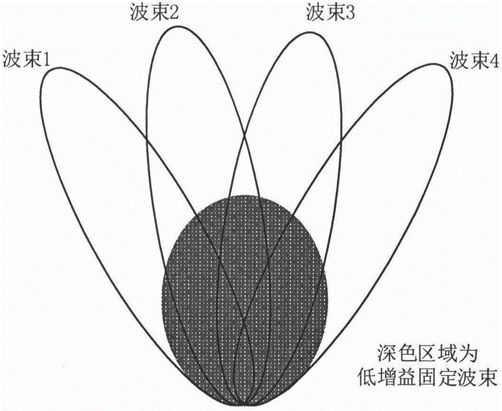
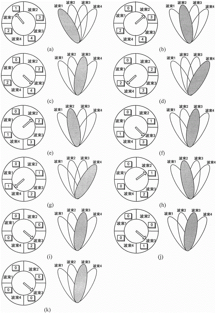
[0021] The gist of the present invention is to propose a smart antenna adaptive control algorithm with a fixed dwell time, which can determine the dwell time and scanning interval of the beam according to the number of tags in each beam direction, communication time, etc., to achieve automatic Adapt to the purpose of controlling the beam, and at the same time reduce the recognition time, improve the tag recognition rate, and reduce energy consumption. The embodiments of the present invention will be further described in detail below in conjunction with the accompanying drawings.

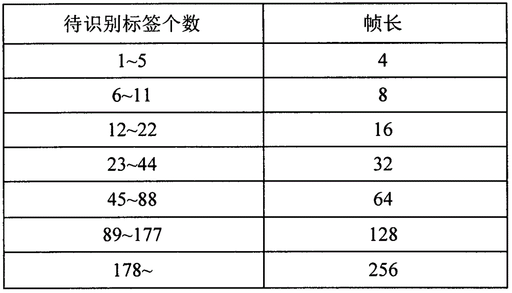
[0022] 1. Chebyshev inequality algorithm estimates the number of labels

[0023] Assuming that there are a total of n tags to be identified within the recognition range of the reader, and the frame length is L, the probability of r tags occupying a time slot obeys the binomial distribution, namely:

[0024] P ( r , n ,...


PUM


Abstract

The invention relates to a smart antenna self-adaptive control algorithm of fixed dwell time. The smart antenna self-adaptive control algorithm belongs to the technical field of RF communication and antennas. The smart antenna self-adaptive control algorithm utilizes a Chebyshev inequation for estimating the number of tags, selects the optimal frame length according to a frame slotted ALOHA algorithm, calculates the number of scanning times required for each beam, realizes beam switching self-adaptive control by adopting a circular queue method, and achieves the purpose of tag self-adaptive recognition. The smart antenna self-adaptive control algorithm can shorten tag recognition time, increase tag recognition rate and reduce energy consumption, and has important significance and wide application prospect in UHF RFID system recognition.

Description

technical field [0001] The invention belongs to the field of radio frequency communication and antenna technology, and in particular relates to an adaptive control algorithm of an intelligent antenna with a fixed dwell time. Background technique [0002] RFID (Radio Frequency Identification) technology uses radio frequency signals to conduct non-contact two-way communication, automatically identify target objects and obtain relevant information data, and has been successfully applied in various fields such as manufacturing, logistics and warehousing, transportation, medical and health, and public safety. It uses the spatial coupling of radio frequency signals to realize contactless data transmission, and achieves the purpose of identifying objects through the mutual transmission of information. [0003] The maximum recognition distance of commonly used readers is about 10 meters, and the total recognition area is limited, which cannot meet the needs of most users, thus limit...

Claims


Application Information

Patent Timeline
Patent Type & Authority Applications(China)
IPC IPC(8): G06K7/00G06K7/10
CPCG06K7/0008G06K7/10079
Inventor 李建雄闫必行陈明省宋战伟韩晓迪刘鹏学
Owner TIANJIN POLYTECHNIC UNIV
Why Eureka
Try Eureka