Saturated steam catalytic burner used for cement decomposition furnace

A technology of cement decomposition furnace and catalytic burner, which is applied in the direction of burning powder fuel burners, burners, and solid fuel combustion, etc., which can solve the problems of poor swirling effect, heat waste, and increased coal consumption, so as to reduce erosion and wear strength, suppress fuel-type NOx, and improve service life

Active Publication Date: 2016-09-21
上海三融环保工程有限公司
View PDF7 Cites 4 Cited by
  • Summary
  • Abstract
  • Description
  • Claims
  • Application Information

AI Technical Summary

Problems solved by technology

[0002] At present, the design volume of early calciners in cement plants is generally small, and in order to control production costs, enterprises have to use cheaper low-quality bituminous coal or anthracite, resulting in incomplete combustion of coal powder; and the burners currently used are all in When the excess air coefficient (that is, the ratio of the actual air supplied to the theoretical air during fuel combustion) is greater than 1, the combustion of pulverized coal and the heating and decomposition of raw materials are carried out. What’s more, the kiln tail still uses the traditional three channel burner (using the primary fan at the kiln tail for air supply), and the CaCO in the calciner 3 The decomposition temperature ranges from 825 to 900°C. It does not need to generate local high temperature like kiln head burners. Once local high temperature is generated, it will cause skinning in the system and waste heat, increase coal consumption, and generate a large amount of NOx, increasing Increased the sewage charges of the cement plant, but also increased the operating cost of the entire cement plant
[0003] At present, some domestic cement plant calciner burners have removed the primary fan at the kiln tail, but only use swirling air fins at the outlet of the burner nozzle to forcibly change the swirling direction of the coal air to achieve the purpose of more fully mixing the coal air. There are the following problems: First, adding "swirl air fins" in the front section of the burner will increase the resistance of the coal air outlet, so that the coal air volume cannot be continuously and stably injected into the calciner, and the service life of the swirl air fins is short and wears out quickly. When worn out or worn seriously, the swirling effect will be worse, and the coal mixing effect will drop significantly

Method used


Image

  • Saturated steam catalytic burner used for cement decomposition furnace
  • Saturated steam catalytic burner used for cement decomposition furnace
  • Saturated steam catalytic burner used for cement decomposition furnace

Examples


Embodiment Construction

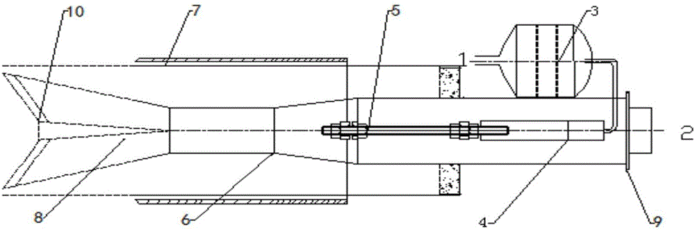
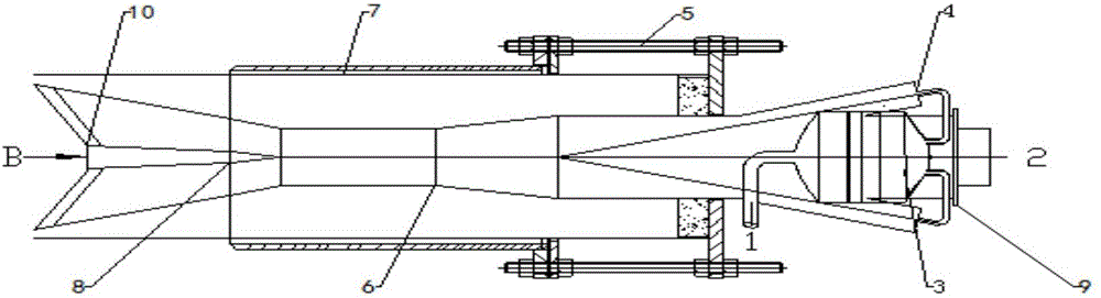
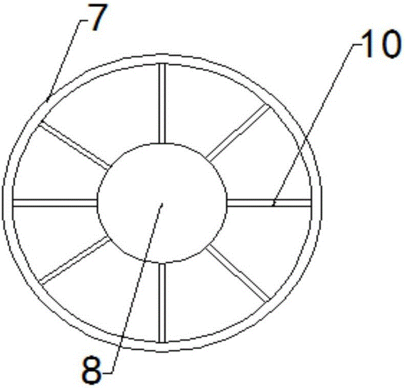
[0026] like figure 1 and figure 2 As shown, a saturated steam catalytic combustor for a cement decomposition furnace of the present invention includes: an inner sleeve 6 , a saturated steam channel 4 , a catalyst tank 3 , a conical chamfer 8 , and a swirling air fin 10 . Wherein, the catalyst tank 3 is connected with the saturated steam channel 4, and the saturated steam channel 4 is connected with the inner sleeve 6 (the connection position between the saturated steam channel 4 and the inner sleeve 6 is located at the front section of the inner sleeve 6 at the diameter change), and the inner sleeve 6 The outlet end is provided with a conical chamfer 8 and a swirl air fin 10 . The saturated steam 1 enters the saturated steam channel 4 through the catalyst tank 3 in two ways. Catalyst tank 3 is equipped with a catalyst to promote the reaction between pulverized coal and saturated steam, and catalyst tank 3 plays a role in adjusting the resistance and flow rate of saturated s...


PUM


Abstract

The invention discloses a saturated steam catalytic burner used for a cement decomposition furnace. The burner comprises an inner sleeve, a saturated steam channel, a catalyst tank, a conical chamfer and cyclone wind wings; the catalyst tank is connected with the saturated steam channel which is connected with the inner sleeve; and the outlet end of the inner sleeve is provided with the conical chamfer and the cyclone wind wings; saturated steam enters the saturated steam channel through the catalyst tank; coal air enters the inner sleeve from the inlet end of the inner sleeve, after the coal air is mixed with the saturated steam coming from the saturated steam channel at the variable-diameter position of the inner sleeve, the diffusion degree of coal powder is increased through the conical chamfer; meanwhile, by means of the cyclone wind wings, the coal powder and the saturated steam rotationally enter the decomposition furnace; and a backflow area is formed at the end portion of a coal pipe, and the purpose of generating CO and H2 is achieved. The saturated steam catalytic burner reduces the generation amount of fuel type nitrogen oxides, reduction components generated after the saturated steam is added can reduce more generated NOx, and the sewage charge and the running cost of a whole cement factory are reduced.

Description

technical field [0001] The invention relates to the field of environmental protection engineering, in particular to a saturated steam catalytic burner, in particular to a saturated steam catalytic burner used in a cement decomposition furnace. Background technique [0002] At present, the design volume of early calciners in cement plants is generally small, and in order to control production costs, enterprises have to use cheaper low-quality bituminous coal or anthracite, resulting in incomplete combustion of coal powder; and the burners currently used are all in When the excess air coefficient (that is, the ratio of the actual air supplied to the theoretical air during fuel combustion) is greater than 1, the combustion of pulverized coal and the heating and decomposition of raw materials are carried out. What's more, the kiln tail still uses the traditional three channel burner (using the primary fan at the kiln tail for air supply), and the CaCO in the calciner 3 The deco...

Claims


Application Information

Patent Timeline
IPC IPC(8): F23D1/02F23B90/06F23K3/02F23L7/00
CPCF23B90/06F23D1/02F23K3/02F23K2203/201F23K2900/05081F23L7/005F23L2900/07009
Inventor 曾赐福陈德志苗娜张雁忠张怀伟
Owner 上海三融环保工程有限公司
Why Eureka
Try Eureka