
Alumina coated cutting tool

A coating cutting tool and coating technology, which is applied in the field of alumina coating cutting tools, can solve the problems of increasing production costs and the like

Inactive Publication Date: 2016-09-14
SANDVIK INTPROP AB
View PDF26 Cites 15 Cited by
  • Summary
  • Abstract
  • Description
  • Claims
  • Application Information

AI Technical Summary

Problems solved by technology

The coating is described as showing good machinability, however, it is generally known that, in addition to Al oxides, the deposition of Zr oxides increases production costs and poses operational safety concerns due to the inherent flammability of freshly polished Zr high requirements

Method used


Image

  • Alumina coated cutting tool
  • Alumina coated cutting tool
  • Alumina coated cutting tool

Examples


Embodiment Construction

[0042] As mentioned above, the α-Al of the present invention 2 o 3 layer, at least in said first thickness portion, having said α-Al produced by said first processing condition 2 o 3 The preferred growth orientation of the grains along the first crystal direction, and the α-Al 2 o 3 The overall fiber texture of the layer is determined by these first processing conditions. Therefore, in a preferred embodiment of the present invention, extending to the α-Al 2 o 3 α-Al on the outer surface of the layer 2 o 3 At least 70%, preferably at least 80%, more preferably at least 90% of the crystals exhibit faces terminated by crystal planes perpendicular to the axis at 0 to 30 degrees, preferably 0 to 30 degrees, to the normal to the substrate surface 20 degrees, more preferably 0 to 10 degrees, measurable by EBSD. In one embodiment of the invention, said first crystallographic orientation is and said planes are terminated by {0 0 1} crystal planes.

[0043] In yet another pre...


PUM

PropertyMeasurementUnit
roughnessaaaaaaaaaa
roughnessaaaaaaaaaa
roughnessaaaaaaaaaa

Abstract

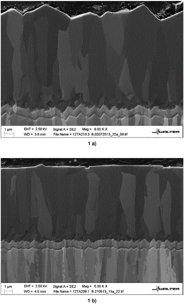
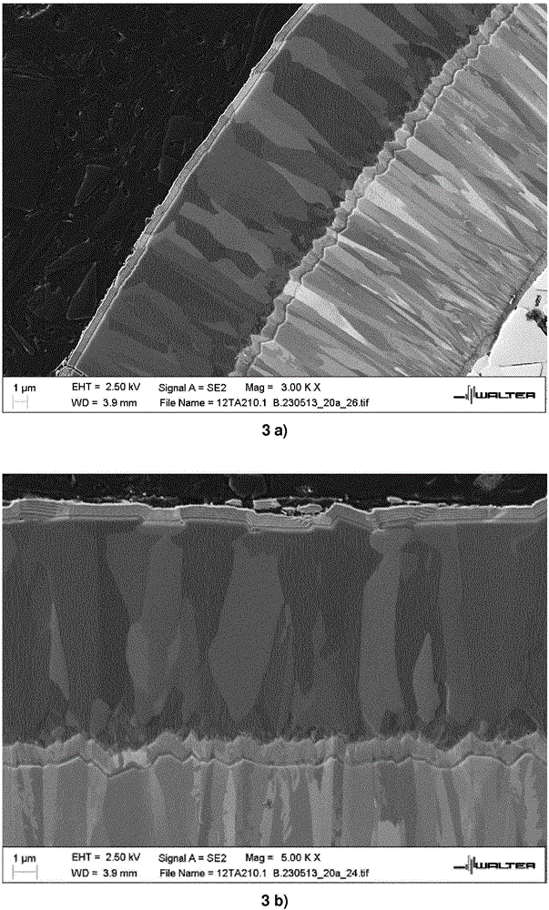
A coated cutting tool insert consisting of a substrate comprising cemented carbide, cermet, ceramics, steel or cubic boron nitride having deposited thereon a coating of a total thickness of a maximum of 60 [mu]m comprising one or more layers comprising a wear resistant layer of alpha-Al2O3 of a thickness of 1 to 45 [mu]m deposited by chemical vapour deposition (CVD), wherein when observed in a SEM microphotograph of a cross section of the alpha-Al2O3 layer, the alpha-Al2O3 layer comprises at least two portions, a first thickness portion and a second thickness portion immediately on top of the first thickness portion, the first thickness portion having an essentially columnar alpha-Al2O3 grain structure, and at the transition from the first thickness portion to the second thickness portion the grain boundaries of at least 1 out of 25 neighbouring grains, preferably of at least 5 out of 25 neighbouring grains, more preferable of at least 15 out of 25 neighbouring grains, of the alpha-Al2O3 grains undergo a directional change into a direction that is essentially perpendicular to the grain boundaries in the first thickness portion, wherein essentially perpendicular includes a directional change of 90 + / - 45 degrees, preferably 90 + / - 30 degrees.

Description

technical field [0001] The present invention relates to a coated cutting tool insert consisting of a substrate comprising cemented carbide, cermet, ceramic, steel or cubic boron nitride, said substrate being at least partially coated Coating with a total thickness of up to 60 μm consisting of one or more layers comprising α-Al deposited by chemical vapor deposition (CVD) with a thickness of 2 to 45 μm 2 o 3 wear layer. Background technique [0002] In the early 1990s, α-Al was realized on an industrial scale 2 o 3 Control of polymorphism, based on the commercial products of US patents 5137774, US 5654035, US 5980988, US 7442431 and US 5863640 describing α-Al with preferred fiber texture 2 o 3 Coating deposition. US 6333103 describes the control of α-Al 2 o 3 Improved methods for nucleation and growth on the (1 0 10) plane. US 6869668 describes the use of ZrCl 4 As a texture modifier in α-Al 2 o 3 A method to obtain a strong (1 0 0) texture in . The prior art met...

Claims


Application Information

Patent Timeline
Patent Type & Authority Applications(China)
IPC IPC(8): C23C16/40
CPCC23C16/403C23C16/45557C23C28/044C23C30/005B23B27/14C23C16/40C23C16/44B23B27/148B23B2222/28B23B2224/04B23B2228/04B23B2228/08C30B25/18C30B29/20C30B29/68
Inventor 萨卡里·鲁皮欣德里克·恩斯特伦乔纳斯·劳里德森奥斯卡·阿尔姆彼得·马特森托米·拉尔森埃里克·林达尔扬·恩奎斯特德克·施廷斯
Owner SANDVIK INTPROP AB
Learn More