Herringbone gear with annular oil storage cavity

A technology of herringbone gears and oil storage chambers, applied to elements with teeth, belts/chains/gears, gear lubrication/cooling, etc., can solve the problem of affecting the strength and life of gears, destroying gear structures, and stress concentration in oil storage chambers and other issues to achieve the effect of reducing processing costs

Inactive Publication Date: 2016-09-14
TAIZHOU JINXIN MACHINERY
View PDF8 Cites 0 Cited by
  • Summary
  • Abstract
  • Description
  • Claims
  • Application Information

AI Technical Summary

Problems solved by technology

However, this kind of gear will destroy the structure of the gear, which will inevitably cause stress concentration around the oil storage chamber, which will affect the strength and life of the gear.

Method used


Image

  • Herringbone gear with annular oil storage cavity
  • Herringbone gear with annular oil storage cavity
  • Herringbone gear with annular oil storage cavity

Examples


Embodiment 1

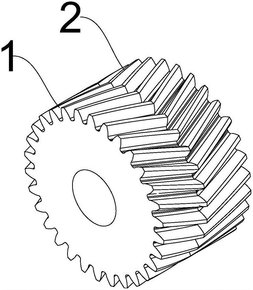
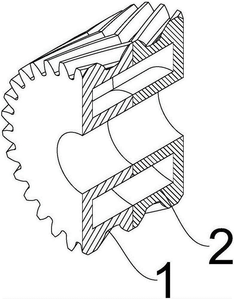
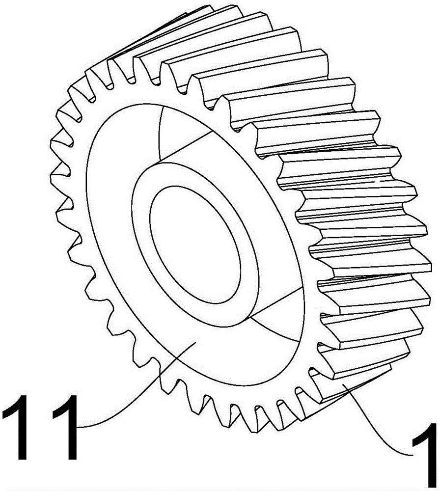
[0020] Such as figure 1 , figure 2 As shown, a herringbone gear with an annular oil storage chamber includes a left part 1 and a right part 2, the left part 1 and the right part 2 are mirror images of each other, as image 3 As shown, an annular groove 11 is provided on the fitting surface of the left part 1, and an annular groove 11 is also provided on the fitting surface of the right part 2 (not shown in the drawings), and the two annular grooves 11 are combined into one The annular oil storage chamber is filled with lubricating oil. When the herringbone gear with the annular oil storage chamber rotates, the lubricating oil in the annular oil storage chamber will flow to the periphery of the annular oil storage chamber under the action of centrifugal force. Since the direction of the axial force on the left part 1 and the right part 2 is opposite, as the herringbone gear with the annular oil storage chamber rotates, the gap between the left part 1 and the right part 2 wil...

Embodiment 2

[0022] On the basis of the first embodiment, the herringbone gear with an annular cavity further includes a gasket 3 arranged between the left part 1 and the right part 2 . In the first embodiment, the left part 1 and the right part 2 are directly connected, and there is only one joint, and the oil discharge speed is relatively slow. By adding the gasket 3, a joint can be added to increase the oil discharge speed. A plurality of spacers 3 can also be added to achieve a higher oil output speed. However, there are too many gaskets, and the lubricating oil pumped out between the gasket seams far from the left part 1 or the right part 2 cannot reach the surface of the gear teeth smoothly and cannot achieve the corresponding lubricating effect, so It is recommended that the number of spacers 3 does not exceed five.


PUM


Abstract

The invention discloses a herringbone gear with an annular oil storage cavity. The herringbone gear comprises a left part and a right part; the left part and the right part are mutually mirror images; annular grooves are formed in the bonding surfaces of the left part and the right part; and the two annular grooves are combined to the annular oil storage cavity. The herringbone gear with the annular oil storage cavity has the following advantages: the herringbone gear adopts a split structure consisting of the left part and the right part, can largely reduce the machining cost, is provided with the oil storage cavity inside, and can slowly supply lubricating oil into gear teeth by using a gap between the left part and the right part to achieve a self-lubricating effect.

Description

technical field [0001] The invention relates to a herringbone gear, more precisely a herringbone gear with an annular oil storage chamber. Background technique [0002] The herringbone gear not only has the advantages of stable helical gear operation, low noise, and is suitable for high-speed and heavy-duty transmission, but also overcomes the shortcomings of helical gears that generate large axial forces; but the herringbone gear also has processing difficulties and relatively high cost. High disadvantage. Chinese invention patent application CN201410356874.0 discloses a self-lubricating gear, including a gear body, the gear body is provided with at least one oil storage chamber, the oil storage chamber communicates with at least two oil passages, and the oil outlets of the two oil passages They are respectively located at the bottom of the alveolar groove, and the gear body is provided with an oil injection screw hole communicating with the oil storage chamber, and the oi...

Claims


Application Information

Patent Timeline
Patent Type & Authority Applications(China)
IPC IPC(8): F16H55/17F16H57/04
CPCF16H55/17F16H57/043
Inventor 陈茂进陈国华
Owner TAIZHOU JINXIN MACHINERY
Why Eureka
Try Eureka