
Data processing method, related equipment and system in Ethernet

A data processing and Ethernet technology, applied in the field of communication, can solve problems such as clock frequency jitter and drift index degradation, achieve the effect of reducing jitter and drift, reducing difficulty, and improving user experience

Active Publication Date: 2016-09-07
HUAWEI TECH CO LTD
View PDF4 Cites 7 Cited by
  • Summary
  • Abstract
  • Description
  • Claims
  • Application Information

AI Technical Summary

Problems solved by technology

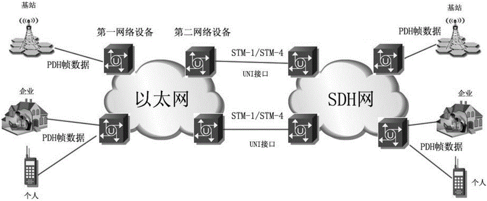
[0006] In the above solution, each PDH frame data transmission from an Ethernet network element to another Ethernet network element connected to SDH requires the following process separately: sampling the clock frequency of the PDH frame data to obtain the difference between the clock frequency of the PDH frame and the Ethernet clock frequency The process of value information, encapsulation, decapsulation, and recovery of the clock frequency of PDH frame data, because at the joint of the UNI port of the first Ethernet network element and the second Ethernet network element, usually multiple PDH frame data will Converge into a synchronous transport module (Synchronous Transport Module, STM) level SDH data flow, therefore, using the above method will face considerable technical challenges in terms of resource implementation and clock frequency recovery performance
At the same time, since the second Ethernet network element needs to use the calculated frequency difference information to restore the clock frequency of the PDH frame data, and the virtual container loaded with the PDH frame data needs to be remapped and multiplexed, this will inevitably result in multiple restorations of the PDH frame The data clock frequency and virtual container mapping degrade the jitter and drift indicators of the original PDH frame data clock frequency

Method used


Image

  • Data processing method, related equipment and system in Ethernet
  • Data processing method, related equipment and system in Ethernet
  • Data processing method, related equipment and system in Ethernet

Examples


Embodiment Construction

[0053] In order to enable those skilled in the art to better understand the solution of the application, the technical solution in the embodiment of the application will be clearly described below in conjunction with the accompanying drawings in the embodiment of the application. Obviously, the described embodiment is only the embodiment of the application Some examples, but not all examples. Based on the embodiments in this application, all other embodiments obtained by persons of ordinary skill in the art without creative efforts shall fall within the scope of protection of this application.

[0054] The "first", "second" and the like mentioned in the embodiments of the present application (if any) are used to distinguish similar objects, and are not necessarily used to describe a specific order or sequence. It is to be understood that the terms so used are interchangeable under appropriate circumstances such that the embodiments described herein can be practiced in sequence...


PUM


Abstract

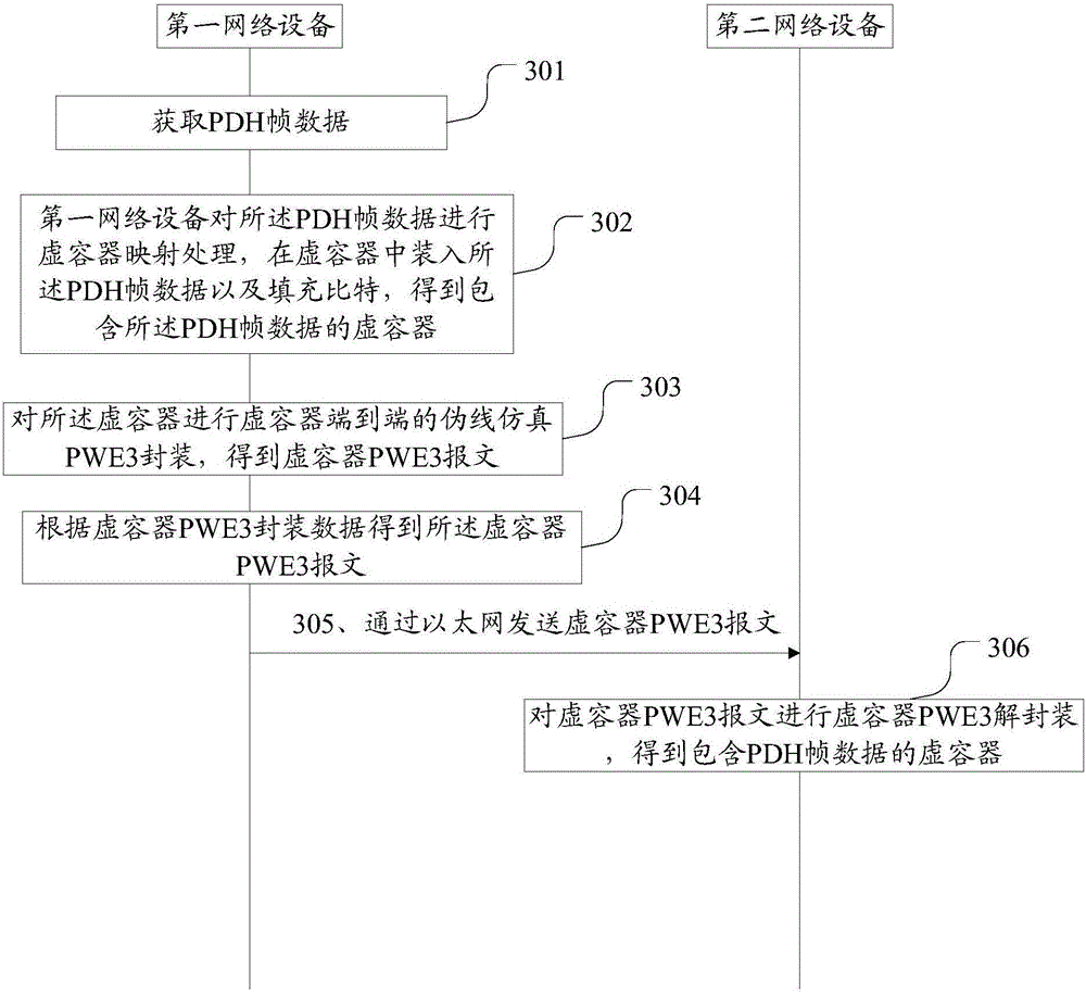
The embodiment of the invention discloses a data processing method, related equipment and system in the Ethernet. The method comprises the steps: enabling first network equipment to receive PDH frame data, enabling the first network equipment to carrying out the virtual container mapping of the PDH frame data, storing the PDH frame data and a filling bit in a virtual container, obtaining the virtual container comprising the PDH frame data, wherein the filling bit of the virtual container comprises the clock frequency difference information between an Ethernet clock frequency and the clock frequency of the PDH frame data; enabling the first network equipment to carry out the PWE3 (Pseudo-Wire Emulation Edge to Edge) package of the virtual container, and obtaining a PWE3 message of the virtual container. According to the embodiment of the invention, the method reduces the difficulty in clock frequency recovery when the PDH data is transmitted in the Ethernet, reduces the jitter and drift, caused by the clock frequency recovery, of the clock frequency, and improves the user experience.

Description

technical field [0001] The present application relates to the field of communication technology, and in particular to a data processing method, related equipment and system in Ethernet. Background technique [0002] With the maturity and evolution of Ethernet packet bearer network technology, mainstream operators have begun to gradually adopt Ethernet packet equipment to the existing Multi-Service Transmission Platform (Multi-Service Transmission Platform, MSTP) and other Time Division Multiplexing (TDM) architectures. Due to factors such as operators' capital investment and network construction plans, Ethernet packet equipment will be integrated with the massive Synchronous Digital Hierarchy (SDH) of the existing network for a long period of time. Mixed networking with MSTP equipment to gradually realize smooth switching of services on the live network. [0003] The hybrid networking network includes Ethernet network elements and SDH / MSTP network elements, where the Ethern...

Claims


Application Information

Patent Timeline
Patent Type & Authority Applications(China)
IPC IPC(8): H04J3/16H04L12/721H04L47/43
CPCH04J3/1635H04L45/68H04J3/06H04J3/16H04J3/073H04L12/46H04J2203/0094H04L12/413H04L12/4625H04L12/4633H04J3/0632H04L12/6418H04L2012/6486
Inventor 张帆周明王辉
Owner HUAWEI TECH CO LTD
Learn More