
A pulse power capacitor

A pulsed power, capacitor technology, applied in the field of capacitors, can solve problems such as low reliability and safety, capacitor cracks, expansion breakdown, etc., to achieve high reliability and safety, prevent expansion breakdown, and increase welding ability.

Active Publication Date: 2018-09-21
FUJIAN TORCH ELECTRON TECH CO LTD
View PDF5 Cites 0 Cited by
  • Summary
  • Abstract
  • Description
  • Claims
  • Application Information

AI Technical Summary

Problems solved by technology

However, the pulse power capacitor with this structure expands due to the heat and ambient temperature changes during the operation of the capacitor. Therefore, the capacitor and the capacitor or between the capacitor and the electrode sheet are easily squeezed due to expansion, and the capacitor is easily damaged by the expansion stress. However, cracks are caused, and there is a danger of expansion breakdown and explosion accidents, and the reliability and safety are low.

Method used


Image

  • A pulse power capacitor
  • A pulse power capacitor
  • A pulse power capacitor

Examples


Embodiment 1

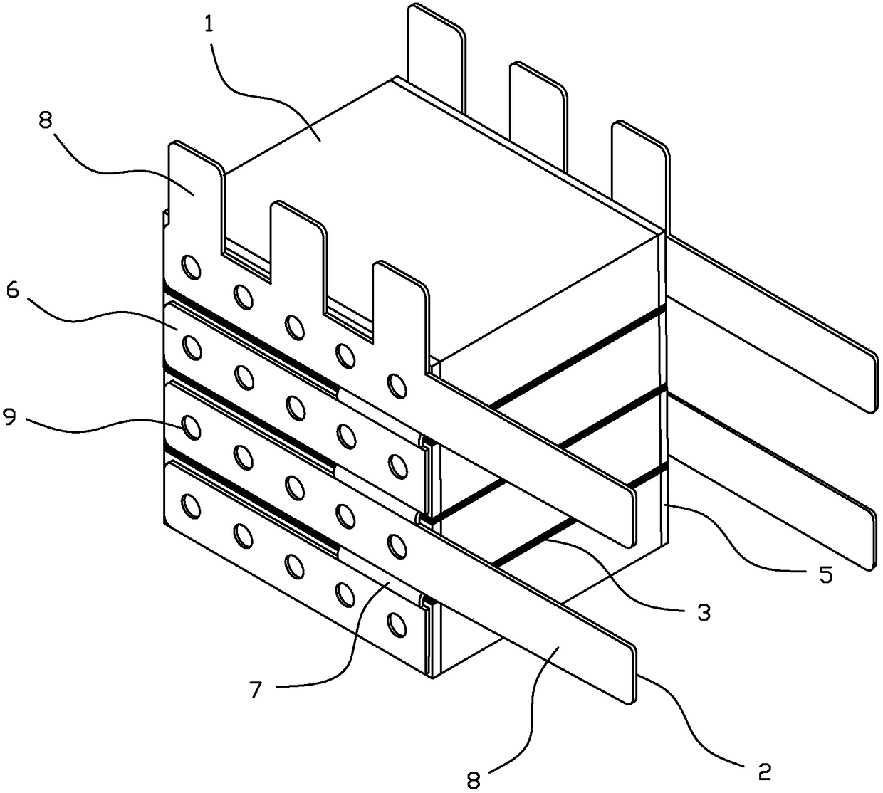
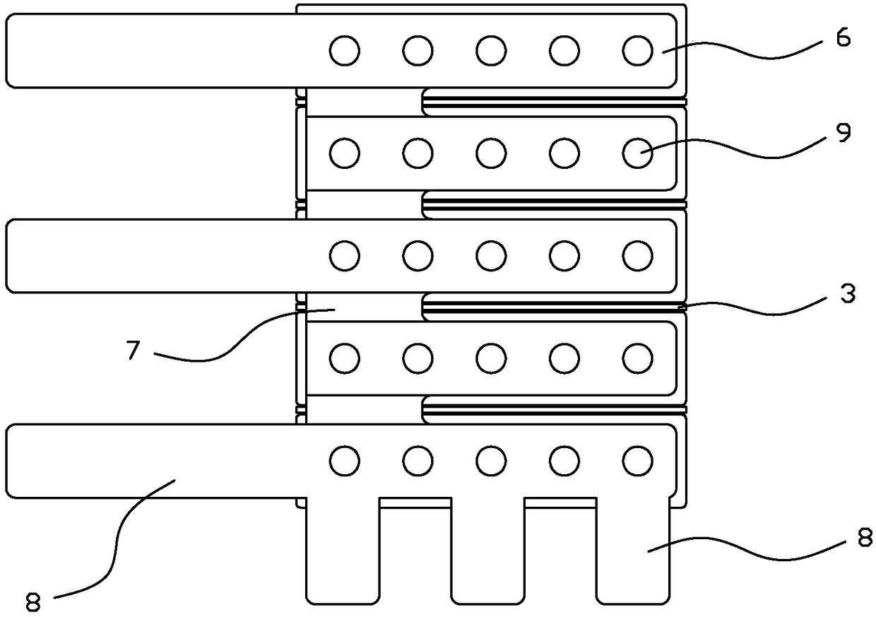
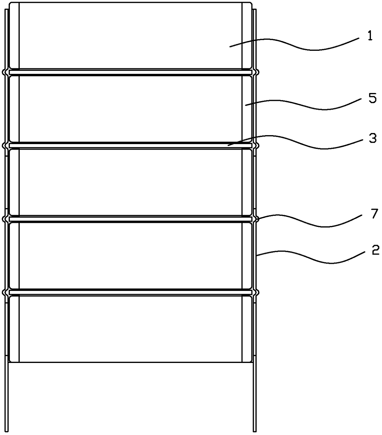
[0035] refer to Figure 1 to Figure 7 A pulse power capacitor of the present invention includes four capacitors 1 and two metal electrode sheets 2, and the four capacitors 1 are stacked and connected in parallel through the two metal electrode sheets 2 to form a parallel capacitor bank. A buffer pad 3 is arranged between two adjacent capacitors 1 , and the buffer pad 3 is made of polytetrafluoroethylene plastic sheet, and is bonded between two adjacent capacitors 1 by red glue 4 . The metal electrode sheet 2 is formed with four electrode plates 6 respectively used to connect the electrodes 5 of the four capacitors 1, the four electrode plates 6 are connected as a whole through the expansion joints 7 connected between two adjacent electrode plates 6, and Several pins 8 are drawn out from the edge of the metal electrode sheet 2 . The electrodes 5 on both sides of the capacitor 1 are respectively welded to the electrode plates 6 of the two metal electrode sheets 2 .

[0036] Th...

Embodiment 2

[0039] refer to Figure 8 and Figure 9 The difference between this embodiment and Embodiment 1 is that a pulse power capacitor in this embodiment includes two capacitors 1 and two metal electrode sheets 2, and the two capacitors 1 are stacked and connected in parallel through two metal electrode sheets 2 to form a parallel connection. capacitor bank. The metal electrode sheet 2 is formed with two electrode plates 6 respectively used to connect the electrodes 5 of the two capacitors 1 , and the two electrode plates 6 are connected as a whole through an expansion joint 7 connected between the two electrode plates 6 . One pin 8 is formed on the side of the metal electrode sheet 2 and three pins 8 are formed on the bottom.

Embodiment 3

[0041] refer to Figure 10 and Figure 11 The difference between this embodiment and Embodiment 1 is that a pulse power capacitor in this embodiment includes five capacitors 1 and two metal electrode sheets 2, and five capacitors 1 are stacked and formed by connecting two metal electrode sheets 2 in parallel. Parallel capacitor bank. The metal electrode sheet 2 is formed with five electrode plates 6 respectively used to connect the electrodes 5 of five capacitors 1 , and the five electrode plates 6 are connected as a whole through expansion joints 7 connected between two adjacent electrode plates 6 . Three pins 8 are formed on the side of the metal electrode sheet 2 , and three pins 8 are formed on the bottom.


PUM


Abstract

A pulse power capacitor, including several capacitors and two metal electrode sheets, several capacitors are connected in parallel through the two metal electrode sheets to form a parallel capacitor bank, several capacitors are stacked, and buffer pads are arranged between adjacent two capacitors, electrodes on both sides of the capacitor They are respectively connected to two metal electrode sheets, and the metal electrode sheet is formed with several electrode plates for connecting capacitor electrodes, and several electrode plates are connected as a whole through expansion joints connected between two adjacent electrode plates, and are led out from the edge of the metal electrode sheet several pins. The present invention can effectively buffer the expansion that occurs when the capacitor is in operation by setting a cushion plate between two adjacent capacitors and connecting the two adjacent electrode plates through an expansion joint, so that the gap between the capacitor and the capacitor and between the capacitor and the metal can be effectively buffered. The electrode sheets have better expansion buffering capacity, are not easy to separate from each other due to expansion, and can effectively prevent capacitor breakdown and explosion caused by expansion, with higher reliability and safety.

Description

technical field [0001] The invention relates to a capacitor, in particular to a pulse power capacitor. Background technique [0002] At present, in the existing pulse power capacitors, in order to increase the capacitor capacitance and energy storage energy, multiple capacitors are usually connected in parallel as energy storage units, and usually multiple capacitors are connected in parallel through electrode sheets connected to capacitor electrodes. However, the pulse power capacitor with this structure expands due to the heating of the capacitor and the change of the ambient temperature during operation. Therefore, the capacitor and the capacitor or between the capacitor and the electrode sheet are easily squeezed due to expansion, and the capacitor is easily damaged by the expansion stress. However, cracks are caused, and there is a danger of expansion breakdown and explosion accidents, and the reliability and safety are low. Contents of the invention [0003] The mai...

Claims


Application Information

Patent Timeline
Patent Type & Authority Patents(China)
IPC IPC(8): H01G4/38
CPCH01G4/38
Inventor 贺卫东郑惠茹张子山蔡劲军
Owner FUJIAN TORCH ELECTRON TECH CO LTD
Learn More