
Welding fixture for friction stir welding of water channels of water-cooled motor shell and annular welding technology

A water-cooled motor and welding fixture technology, applied in welding equipment, non-electric welding equipment, manufacturing tools, etc., can solve the problems of time-consuming and laborious loading and unloading of workpieces, low welding efficiency, poor positioning stability of workpieces, etc., to reduce manufacturing costs and improve welding Efficiency, the effect of improving production efficiency

Active Publication Date: 2016-09-07
中色创新研究院(天津)有限公司
View PDF7 Cites 5 Cited by
  • Summary
  • Abstract
  • Description
  • Claims
  • Application Information

AI Technical Summary

Problems solved by technology

However, there are still some deficiencies in the current friction stir welding welding process and equipment for water-cooled motor casings. First, the design of most welding fixtures is relatively cumbersome, the positioning stability of the workpiece is poor, and the workpiece is prone to deformation during welding; secondly, only Welding each water channel one by one, the degree of automation is low, and circular continuous welding cannot be realized; the loading and unloading process of the final workpiece is also time-consuming and laborious, resulting in low welding efficiency and high cost

Method used


Image

  • Welding fixture for friction stir welding of water channels of water-cooled motor shell and annular welding technology
  • Welding fixture for friction stir welding of water channels of water-cooled motor shell and annular welding technology

Examples


Embodiment Construction

[0023] The specific implementation of the present invention will be described in detail below in conjunction with preferred embodiments.

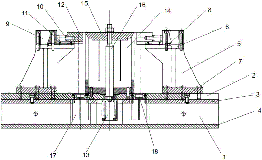
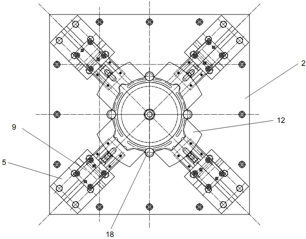
[0024] See the accompanying drawings for details, a welding fixture for friction stir welding of water-cooled motor shells, including a fixture base, an oil cylinder support mechanism, a top block clamping mechanism, an expansion sleeve locking mechanism and a PLC control system. The oil cylinder support mechanism includes four An oil cylinder support seat arranged in a cross, the oil cylinder support seat is fixedly connected to the fixture base; a top block clamping mechanism is fixedly connected to the oil cylinder support mechanism, and the top block clamping mechanism includes a thin horizontal oil cylinder and a linear guide rail and the top block of the oil cylinder, the thin horizontal oil cylinder is connected with the linear guide rail through the connecting screw, the linear guide rail is connected with the top block of the oil cy...


PUM


Abstract

The invention relates to a welding fixture for friction stir welding of water channels of a water-cooled motor shell. The welding fixture for friction stir welding of the water channels of the water-cooled motor shell comprises a fixture base, an oil cylinder support mechanism, an ejector block clamping mechanism, a power lock locking mechanism and a PLC system. The ejector block clamping mechanism and the power lock locking mechanism are respectively connected with the PLC system. According to the welding technology, double working tables are alternately used for welding of friction stir welding equipment, by the PLC system, the welding fixture moves along an X-axis guide track of each working table, a stirring head moves along a Y-axis guide track of each working table, and annular continuous welding of the water channels is realized. The welding fixture for friction stir welding of the water channels of the water-cooled motor shell has the beneficial effects that the inner side of a workpiece is locked by an expander sleeve and the center is positioned firmly, an oil cylinder drives an outward ejector block to move along a linear guide track to clamp the outer side of the workpiece, the water-cooled motor shell is ensured not to deform in a clamping process, and the stability of a welding process is also ensured; and the welding fixture moves along the X-axis guide track of each working table and the stirring head moves along the Y-axis guide track of each working table by the friction stir welding equipment through programming, and therefore, annular continuous welding of the water channels is realized.

Description

technical field [0001] The invention belongs to friction stir welding, and in particular relates to a welding fixture and an annular welding process for a friction stir welding channel of a water-cooled motor casing. Background technique [0002] Friction stir welding is an innovative and advanced friction welding technology, known as "green welding technology" with high quality and low cost. Compared with traditional welding methods, friction stir welding has the advantages of high welding strength, smooth appearance of welded joints, small residual stress after welding, small deformation, no pollution, high efficiency and energy saving. The aluminum alloy water-cooled motor housing has high requirements for the welding quality of the water channel end face. The weld surface is required to be smooth, the sealing performance is good, the microstructure is uniform, and no porosity defects are allowed. Therefore, friction stir welding is mostly used for water channel welding o...

Claims


Application Information

Patent Timeline
Patent Type & Authority Applications(China)
IPC IPC(8): B23K20/12
CPCB23K20/1245B23K20/126
Inventor 李永林王金钟吕涛杨永刚刘冲霄杨涛宋灏王世全
Owner 中色创新研究院(天津)有限公司
Learn More