Control method, control circuit, backlight integration circuit and terminal equipment
A control method and control circuit technology, applied in the field of communication, can solve the problems of low maximum brightness and low minimum brightness of the screen, and achieve the effects of maintaining current stability, large regulation range, and fine current control
- Summary
- Abstract
- Description
- Claims
- Application Information
AI Technical Summary
Problems solved by technology
Method used
Image
Examples
no. 1 example
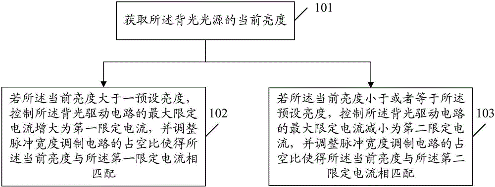
[0039] Such as figure 1 As shown, the first embodiment of the present invention provides a control method for a backlight driving circuit, the backlight driving circuit is connected with a backlight light source and a pulse width modulation circuit, including:
[0040] Step 101, acquiring the current brightness of the backlight light source.
[0041] In this step, the backlight light source usually consists of one or more backlight LED (Light Emitting Diode) strings. Then the current brightness of the backlight light source is the brightness of the backlight LED light string, which can also be understood as the brightness of the screen or display screen of the terminal device.
[0042] Step 102, if the current brightness is greater than a preset brightness, control the maximum limit current of the backlight drive circuit to increase to a first limit current, and adjust the duty cycle of the pulse width modulation circuit so that the current brightness is the same as the The ...
no. 2 example
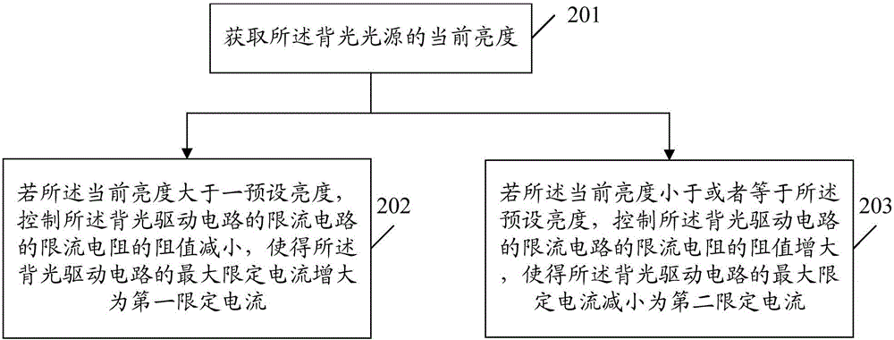
[0060] Such as figure 2 As shown, the second embodiment of the present invention also provides a control method of a backlight driving circuit, the backlight driving circuit is connected with a backlight light source and a pulse width modulation circuit, including:
[0061] Step 201, acquiring the current brightness of the backlight light source.
[0062] In this step, the backlight light source of the backlight driving circuit usually consists of one or more backlight LED (light emitting diode) strings. Then the current brightness of the backlight light source is the brightness of the backlight LED light string, which can also be understood as the brightness of the screen or display screen of the terminal device.
[0063] Step 202, if the current brightness is greater than a preset brightness, control the resistance of the current limiting resistor of the current limiting circuit of the backlight driving circuit to decrease, so that the maximum limited current of the backli...
no. 3 example
[0072] Such as image 3 As shown, the third embodiment of the present invention provides a control circuit of a backlight driving circuit, the backlight driving circuit is connected with the backlight light source and the pulse width modulation circuit, and the control circuit includes:
[0073] An acquisition module 301, configured to acquire the current brightness of the backlight light source;
[0074] The first control module 302 is configured to control the maximum limited current of the backlight drive circuit to increase to a first limited current if the current brightness is greater than a preset brightness, and adjust the duty cycle of the pulse width modulation circuit so that the The current brightness matches the first limited current;
[0075] The second control module 303 is configured to control the maximum limited current of the backlight drive circuit to be reduced to a second limited current if the current brightness is less than or equal to the preset brigh...
PUM
 Abstract
Description
Claims
Application Information
 - Generate Ideas
- Intellectual Property
- Life Sciences
- Materials
- Tech Scout
- Unparalleled Data Quality
- Higher Quality Content
- 60% Fewer Hallucinations
Browse by: Latest US Patents, China's latest patents, Technical Efficacy Thesaurus, Application Domain, Technology Topic, Popular Technical Reports.
© 2025 PatSnap. All rights reserved.Legal|Privacy policy|Modern Slavery Act Transparency Statement|Sitemap|About US| Contact US: help@patsnap.com


