
Butt joint type concrete pole with wire storage function

A cement electric pole and docking technology, applied in the field of electric equipment manufacturing, can solve the problems of reducing the service life of cement electric poles, affecting the safety performance of cement electric poles, hidden dangers of cement electric poles, etc. , The effect of avoiding core damage

Active Publication Date: 2016-08-31
STATE GRID ZHEJIANG PINGHU POWER SUPPLY +2
View PDF8 Cites 1 Cited by
  • Summary
  • Abstract
  • Description
  • Claims
  • Application Information

AI Technical Summary

Problems solved by technology

Corrosion of the steel ring reduces the strength of the butt joint and poses a safety hazard to the cement pole
On the other hand, the expansion coefficient and physical and chemical properties of the steel ring and cement are very different. In the natural environment of alternating cold and heat, wind and rain, the cement in contact with the steel ring is easy to weather, so the steel ring The weathering speed of the cement is far greater than the weathering speed of other parts of the cement pole, so that the strength of the cement pole near the steel ring gradually decreases, which affects the safety performance of the cement pole and reduces the service life of the cement pole
[0006] In the process of daily use and maintenance, wiring is often required on cement poles to meet temporary power needs, but every wiring is very troublesome

Method used


Image

  • Butt joint type concrete pole with wire storage function
  • Butt joint type concrete pole with wire storage function
  • Butt joint type concrete pole with wire storage function

Examples


Embodiment Construction

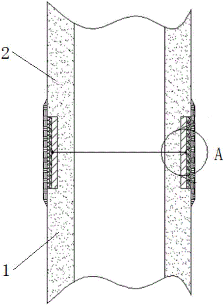
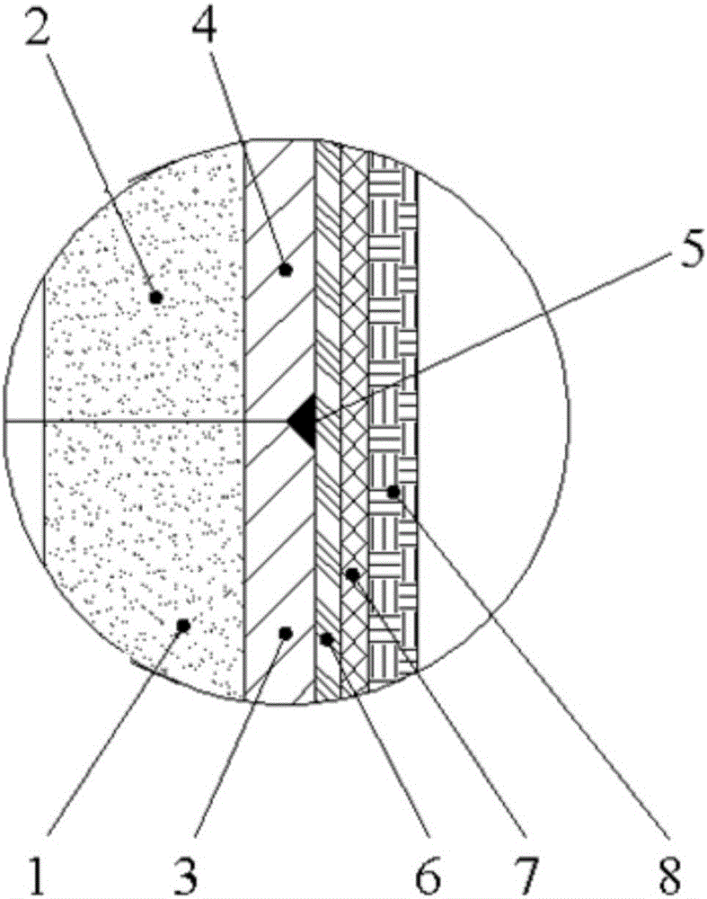
[0033] Such as figure 1 and figure 2 As shown, for super long cement poles that cannot be manufactured as a whole, they are manufactured in sections. In this embodiment, two sections are used, that is, the cement poles are divided into the first pole section 1 and the second pole section 2, and the two pole sections Manufactured separately. The top of the first pole section 1 is provided with a first pole section steel ring 3; the bottom end of the second pole section 2 is provided with a second pole section steel circle 4, and the outer diameters of these two steel circles are exactly the same and less than The outer diameter of the two rod segments.

[0034] The steel plate ring 3 of the first bar section and the steel plate ring 4 of the second bar section are welded to form an integral steel plate fixed ring, and an anti-corrosion treatment layer 6 is coated on the surface of the steel plate fixed ring. An outer protection structure is arranged outside the anticorrosio...


PUM


Abstract

The invention discloses a butt joint type concrete pole with a wire storage function. The butt joint type concrete pole comprises a steel plate fixing ring for fixing a first pole section and a second pole section which are in butt joint. The surface of the steel plate fixing ring is coated with an anti-corrosion treatment layer, and an outer protection structure is arranged outside the anti-corrosion treatment layer. A fixing rod is arranged on the first pole section / second pole section. A wire storage box is movably installed on the fixing rod through a movable adjusting part. The fixing rod comprises a supporting plate. The supporting plate is provided with a row of stop grooves in the front-back direction. The movable adjusting part is provided with a stop tooth which is matched with the stop grooves and positioned on the supporting plate at the same time. The wire storage box comprises a box body internally provided with a wire winder. The wire winder comprises a rotary shaft and a wire reel rotationally connected to the rotary shaft. The first side wall of the box body is provided with a wire inlet. The second side wall of the box body is provided with a wire outlet. The butt joint type concrete pole has the advantages of a good anti-corrosion property, high strength, good waterproofness, long service life and good safety, and meanwhile a wire can be conveniently connected from the concrete pole.

Description

technical field [0001] The invention relates to electric equipment manufacturing technology, and more particularly relates to a butt joint structure of cement poles suitable for assembly on site. Background technique [0002] Modern society is inseparable from electricity. The electricity generated by the power plant must be transmitted to the user end through electric power transmission to ensure the needs of production and life. The pole is an indispensable power equipment in the process of power transmission. [0003] Most of the early electric poles used wooden poles, but with the development of technology, wooden poles have been eliminated and replaced by iron towers and cement poles. Compared with the iron tower, the cement pole can save a lot of steel, reduce the cost of the line, the operation and maintenance are simple, the maintenance workload is small, and the service life is relatively long, up to 30 to 50 years, so the cement pole has great advantages and be m...

Claims


Application Information

Patent Timeline
IPC IPC(8): E04H12/12
CPCE04H12/12
Inventor 倪大伟金朝辉潘建乔胡雷剑栾伊斌吴迪任姚柴慎强朱忠明俞健顾强杰刘训
Owner STATE GRID ZHEJIANG PINGHU POWER SUPPLY
Learn More